Wave beam direction adjustment circuit and method and electronic equipment

A beam direction, adjusting circuit technology, applied in the field of communication, can solve the problem of fixed antenna main beam direction and so on

Pending Publication Date: 2017-12-08
VIVO MOBILE COMM CO LTD
View PDF7 Cites 8 Cited by
  • Summary
  • Abstract
  • Description
  • Claims
  • Application Information

AI Technical Summary

Problems solved by technology

[0004] The embodiment of the present invention provides a beam direction adjustment circuit, electronic equipment and method to solve the problem that the main beam direction of the antenna is relatively fixed

Method used


Image

  • Wave beam direction adjustment circuit and method and electronic equipment
  • Wave beam direction adjustment circuit and method and electronic equipment
  • Wave beam direction adjustment circuit and method and electronic equipment

Examples


Embodiment Construction

[0026] The following will clearly and completely describe the technical solutions in the embodiments of the present invention with reference to the accompanying drawings in the embodiments of the present invention. Obviously, the described embodiments are some of the embodiments of the present invention, but not all of them. Based on the embodiments of the present invention, all other embodiments obtained by persons of ordinary skill in the art without creative efforts fall within the protection scope of the present invention.

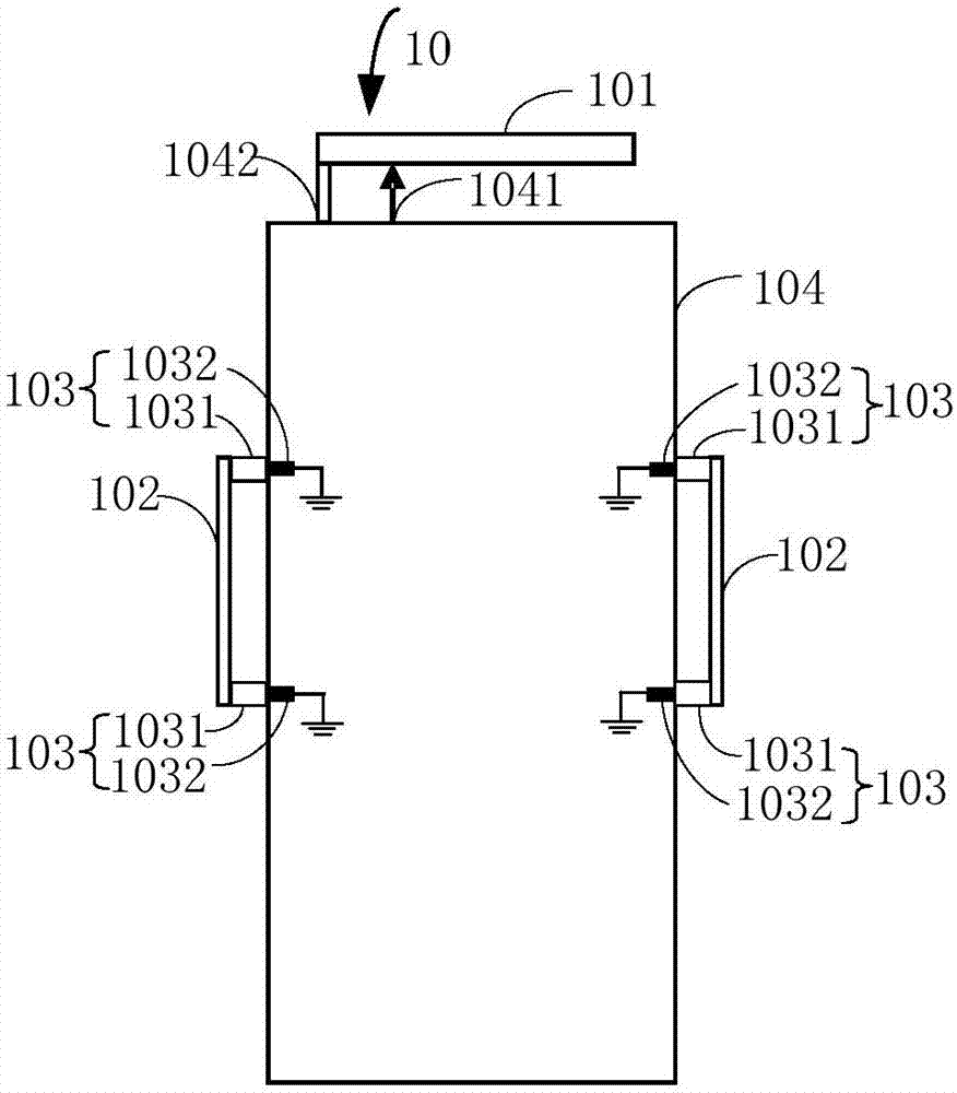
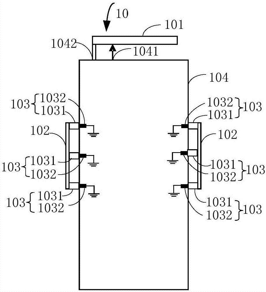
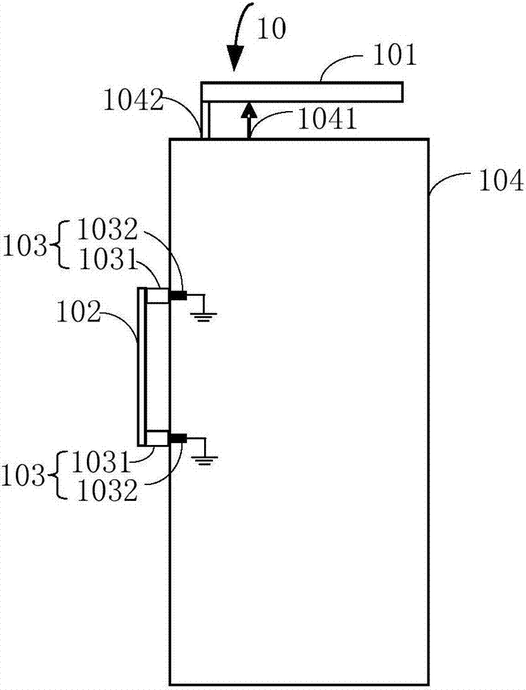
[0027] An embodiment of the present invention provides a beam direction adjustment circuit, see figure 1 , figure 1 is a schematic diagram of the beam direction adjustment circuit provided by the embodiment of the present invention, such as figure 1 As shown, the beam direction adjustment circuit 10 includes an antenna 101, a metal strip 102, an electrically tunable component 103 and a system ground unit 104. The antenna 101 is connected to the system...


PUM


Abstract

The invention provides a wave beam direction adjustment circuit and method and electronic equipment. The wave beam direction adjustment circuit comprises an antenna, metal strips, electric tunable assemblies and a system ground unit, wherein the antenna is connected with the system ground unit, the metal strips are connected with the system ground unit via the electric tunable assemblies, and a preset distance is arranged between the metal strips and the antenna. With the wave beam direction adjustment circuit provided by the invention, the direction of a main wave beam of the antenna can be changed.

Description

technical field [0001] The invention relates to the field of communication technology, in particular to a beam direction adjustment circuit, electronic equipment and method. Background technique [0002] With the development of technology and the progress of society, wireless communication has been closely related to everyone's life, and realizing high-quality wireless communication in different locations has always been a problem faced by wireless communication researchers. At present, the position of the antenna of the electronic device is usually fixed, so the radiation pattern of the antenna is fixed, that is, the direction of the main beam of the antenna is fixed, and cannot be adjusted according to the relative position change of the electronic device and the signal source. Taking the mobile terminal as an example, the radiation pattern of the GNSS (Global Navigation Satellite System, Global Navigation Satellite System) antenna in many mobile terminals, that is, the ma...

Claims


Application Information

Patent Timeline
Patent Type & Authority Applications(China)
IPC IPC(8): H01Q23/00H01Q1/50H01Q3/34
CPCH01Q1/50H01Q3/34H01Q23/00
Inventor 黄奂衢谢宁宁简宪静
Owner VIVO MOBILE COMM CO LTD
Why Eureka
Try Eureka