
High voltage electrical cabinet door sealing device

A high-voltage electrical and electrical cabinet technology, which is applied in the substation/distribution device shell, building fastening devices, construction, etc., can solve the damage of electrical cabinet components, increase the cost of operation and maintenance, and the cabinet door of the electrical cabinet is not sealed, etc. problems, to achieve the effect of prolonging the service life, reducing operation and maintenance costs, and preventing the cabinet door from loosening

Active Publication Date: 2017-12-08
安徽明都能源建设集团有限公司
View PDF5 Cites 5 Cited by
  • Summary
  • Abstract
  • Description
  • Claims
  • Application Information

AI Technical Summary

Problems solved by technology

[0002] At present, the general integrated power distribution cabinets for rural power grids are mainly used in rural and suburban rural distribution networks. It is difficult to solve some problems of low power quality in the rural distribution network, such as the long power supply radius of some power distribution lines and the line loss rate. Higher, larger pressure drop, especially in remote mountainous areas, it becomes particularly important for the normal and safe work of high-voltage electrical cabinets, but because many places are located far away, long-term wind and rain, and long-term back and forth The switch cabinet door of the electrical cabinet is not sealed properly, causing a large amount of rainwater to enter, causing serious damage to the components in the electrical cabinet. At the same time, some small animals will enter the field and cause damage to the grid wires, which will affect the normal operation. use, increase the difficulty of maintenance and increase the cost of operation and maintenance

Method used


Image

  • High voltage electrical cabinet door sealing device
  • High voltage electrical cabinet door sealing device

Examples


Embodiment Construction

[0017] In order to enable those skilled in the art to better understand the technical solutions of the present invention, the present invention will be further described in detail below in conjunction with the accompanying drawings.

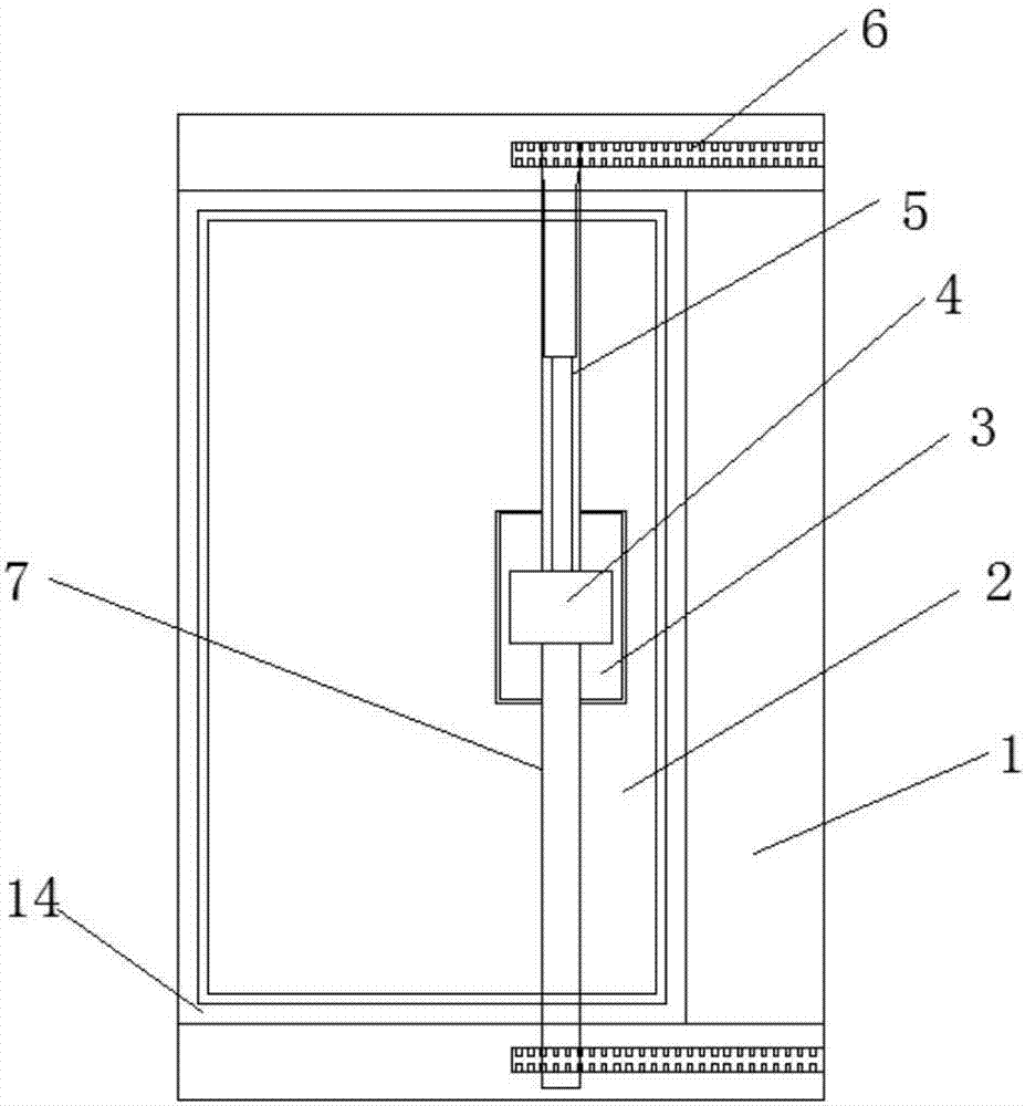
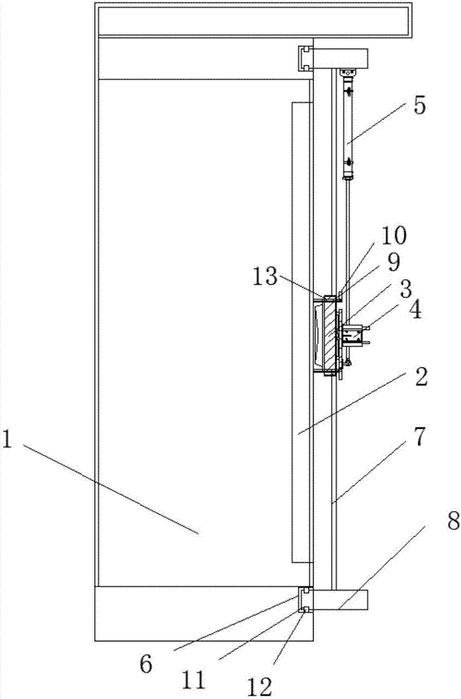
[0018] Please refer to figure 1 , figure 2 , a door sealing device for a high-voltage electrical cabinet door, comprising a high-voltage electrical cabinet 1 and a cabinet door 2, the cabinet door 2 is arranged in a door frame 14 on one side of the high-voltage electrical cabinet 1, and the upper and lower sides of the cabinet door 2 Two sliding fixed blocks 8 are symmetrically arranged on the side of the high-voltage electrical cabinet 1, and a top door device for closing the door 2 of the high-voltage electric cabinet 1 is arranged between the two sliding fixed blocks 8, and the top door device is provided by a horizontal electric push rod 4 and a vertical electric push rod 5, the horizontal electric push rod 4 passes through the sliding rod ...


PUM


Abstract

The objective of the invention is to provide a high voltage electrical cabinet door sealing device comprising a high voltage electrical cabinet and a cabinet door. The cabinet door is arranged in the door frame of one side surface of the high voltage electrical cabinet. The high voltage electrical cabinet side surfaces of the upper and lower sides of the cabinet door are symmetrically provided with two slide fixing blocks. A door jacking device used for sealing the high voltage electrical cabinet door is arranged between the two slide fixing blocks. The door jacking device is composed of a horizontal electric push rod and a vertical electric push rod. The horizontal electric push rod is connected in a way of penetrating through a slide pole arranged between the two slide fixing blocks. An abutting plate is arranged between the horizontal electric push rod and the cabinet door. One end of the vertical electric push rod is connected with the slide fixing blocks, and the other end of the vertical electric push rod is connected with the connecting block of the horizontal electric push rod. Loosening of the cabinet door caused by long-time use can be prevented, the sealing degree can be enhanced, damage to the grid lines and the electrical devices can be prevented, the service life can be prolonged, the maintenance difficulty can be reduced and the operation and maintenance cost can be reduced.

Description

technical field [0001] The invention relates to the field of high-voltage electrical cabinets, in particular to the cabinet door of the high-voltage electrical cabinet, and in particular to a door sealing device for the cabinet door of the high-voltage electrical cabinet. Background technique [0002] At present, the general integrated power distribution cabinets for rural power grids are mainly used in rural and suburban rural distribution networks. It is difficult to solve some problems of low power quality in the rural distribution network, such as the long power supply radius of some power distribution lines and the line loss rate. Higher, larger pressure drop, especially in remote mountainous areas, it becomes particularly important for the normal and safe work of high-voltage electrical cabinets, but because many places are located far away, long-term wind and rain, and long-term back and forth The switch cabinet door of the electrical cabinet is not sealed properly, c...

Claims


Application Information

Patent Timeline
IPC IPC(8): H02B1/30H02B1/28E05C9/04
CPCE05C9/04H02B1/28H02B1/30
Inventor 代宝成马千里罗永华陆浩倪群王先茂
Owner 安徽明都能源建设集团有限公司
Learn More