
Solar switch cabinet

A switchgear, solar energy technology, applied in substation/switch layout details, substation/switchgear cooling/ventilation, electrical components, etc., can solve problems such as high failure rate, shortened service life, etc., to enhance ventilation and reduce aging speed. , reduce the effect of direct sunlight

Pending Publication Date: 2017-12-08
镇江玄润电气设备有限公司
View PDF6 Cites 0 Cited by
  • Summary
  • Abstract
  • Description
  • Claims
  • Application Information

AI Technical Summary

Problems solved by technology

[0002] The switchgear is a widely used device in the supporting power supply. In many cases, the power distribution cabinet is placed outdoors. However, in summer, especially when the sunlight is strong, it will cause high temperature inside the box, and the switchgear The components in the device are aging very quickly, which will greatly shorten their service life and cause a high failure rate

Method used


Image

  • Solar switch cabinet
  • Solar switch cabinet
  • Solar switch cabinet

Examples


Embodiment Construction

[0016] In order to further describe the technical features and effects of the present invention, the present invention will be further described below in conjunction with the accompanying drawings and specific embodiments.

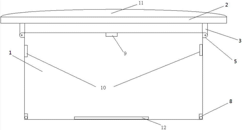
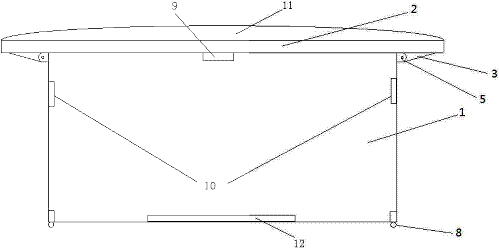
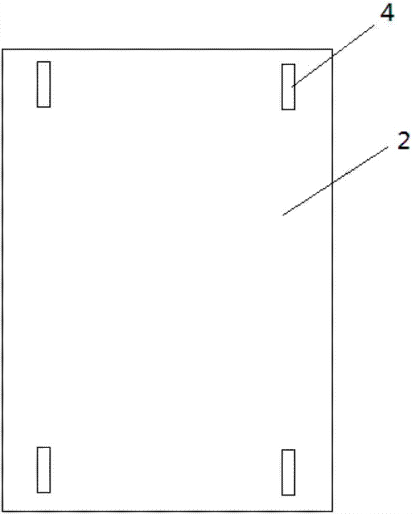
[0017] refer to Figure 1-Figure 4 , a solar switch cabinet, including a box body 1, a baffle plate 2 and a support arm 3, the baffle plate 2 is arranged above the box body 1, a chute 4 is provided below the baffle plate 2, and one end of the support arm 3 slides Clamped in the chute 4, the other end is hinged with the side wall of the box body 1 through the first hinge 5, the hinge 5 is located at the top of the side wall of the box body 1, the inside of the support arm 3 is hollow, and a limit rod 6 is arranged inside it to limit One end of the positioning rod 6 is movably connected with the upper end of the support arm 3 through a rotating shaft, the other end is provided with a magnet 7, a temperature sensor 9 is provided above the casing 1, and an ins...


PUM


Abstract

The invention discloses a solar switch cabinet. The solar switch cabinet comprises a cabinet body, a baffle plate and support arms. The baffle plate is arranged over the cabinet body. Sliding grooves are arranged under the baffle plate. One end of the support arm is clamped inside the sliding groove in a sliding manner and the other end is hinged with a side wall of the cabinet body through a first hinge. Hinges are positioned on the tops of the side walls of the cabinet body. The support arm is internally hollow and a limiting rod is arranged inside the support arm. One end of the limiting rod is movably connected to the upper end of the support arm through a rotation shaft and the other end is provided with a magnet. A temperature sensor is arranged on the upper part of the cabinet body. Installation ports are arranged on two side walls of the cabinet body. An air exhaust air is installed in the installation port, a solar panel is arranged on the surface of the baffle plate and a storage battery is arranged on the bottom of the switch cabinet. The solar switch cabinet can effectively reduce direct solar radiation and can reduce the aging speed of the component inside the switch cabinet, and is easy to displace and easy to place.

Description

technical field [0001] The invention belongs to the technical field of electrical supporting facilities, and in particular relates to a solar switch cabinet. Background technique [0002] The switchgear is a widely used device in the supporting power supply. In many cases, the power distribution cabinet is placed outdoors. However, in summer, especially when the sunlight is strong, it will cause high temperature inside the box, and the switchgear The components in the battery age very quickly, which will greatly shorten its service life and cause a high failure rate. Contents of the invention [0003] In order to solve the above existing problems, the present invention provides a solar switch cabinet, which can effectively avoid direct sunlight and reduce its failure rate, and when the temperature is too high, the daily stored solar energy can be used to enhance the internal ventilation of the cabinet. [0004] The technical problem to be solved by the present invention i...

Claims


Application Information

Patent Timeline
Patent Type & Authority Applications(China)
IPC IPC(8): H02B1/30H02B1/56
CPCH02B1/30H02B1/565
Inventor 高超张伟管鑫焱
Owner 镇江玄润电气设备有限公司
Learn More