Electronic device and circuit board assembly thereof

A technology of circuit board components and substrates, applied in the direction of electrical equipment construction parts, circuit heat parts, printed circuit parts, etc., can solve the problem of limited heat dissipation area, increase heat dissipation area, realize heat conduction, and improve heat dissipation speed Effect

Active Publication Date: 2017-12-08
GUANGDONG OPPO MOBILE TELECOMM CORP LTD
View PDF4 Cites 3 Cited by
  • Summary
  • Abstract
  • Description
  • Claims
  • Application Information

AI Technical Summary

Problems solved by technology

[0004] Embodiments of the present invention can solve the problem of limited heat dissipation area when shielding covers are used to dissipate heat from electronic equipment

Method used


Image

  • Electronic device and circuit board assembly thereof
  • Electronic device and circuit board assembly thereof
  • Electronic device and circuit board assembly thereof

Examples


Embodiment 1

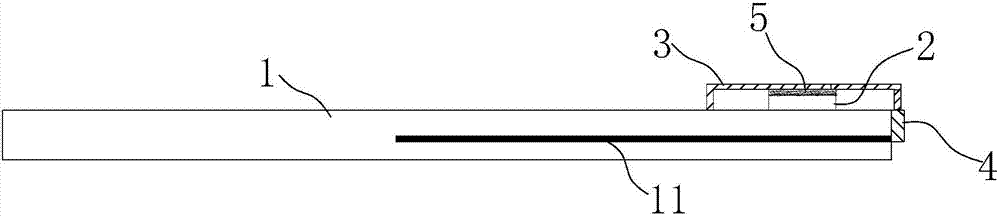
[0026] See figure 1 , this embodiment provides a circuit board assembly, including a substrate 1 , a heating element 2 , a shield 3 and a heat conducting member 4 .

[0027] The heating element 2 is arranged on the surface of the substrate 1, the shielding cover 3 is fixed on the surface of the substrate 1, and the heating element 2 is covered, and a thermal conductive glue 5 is connected between the heating element 2 and the shielding cover 3, and the inside of the substrate 1 has a layer metal layer 11. The shielding cover 3 is bonded to the metal layer 11 inside the substrate 1 through the heat conducting member 4 to realize heat conduction. Wherein, the way of heat conduction in this embodiment may be that the two surfaces are closely attached to each other, or the two may be bonded by a thermally conductive adhesive material.

[0028] Specifically, the thermally conductive adhesive 5 is pasted on the top surface of the heating element 2 , and the top of the thermally co...

Embodiment 2

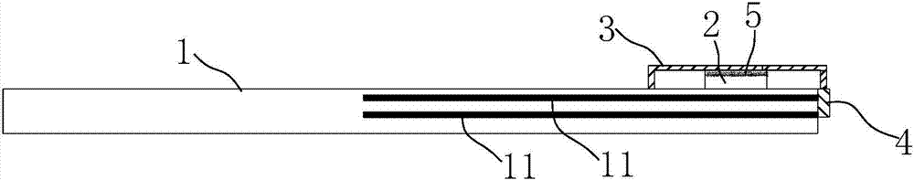
[0033] See image 3 The difference between this embodiment and Embodiment 1 is that two layers of metal layers 11 spaced up and down are arranged inside the substrate 1 of this embodiment, and the sides of the two layers of metal layers 11 are exposed to the side of the substrate 1, and are fixed to the The heat conducting element 4 on the side of the substrate 1 is bonded. Compared with the first embodiment, the heat conduction element 4 of this embodiment is attached to more metal layers 11 , so that the heat can be dispersed to a larger area, and the heat dissipation rate can be further improved.

Embodiment 3

[0035] The difference between this embodiment and Embodiment 1 is that a hole 12 is opened on the substrate 1, and the heat conduction element 4 is embedded in the hole 12. One end of the heat conduction element 4 is attached to the shielding cover 2, and the other end is attached to the metal Layer 11 fits.

[0036] Specifically, this embodiment provides three implementation forms of the above structure:

[0037] For the first form of implementation see Figure 4 , the top of the heat conducting element 4 is attached to the bottom of the shielding case 3 , and the heat conducting adhesive 5 is bonded between the top of the heating element 2 and the top wall of the shielding case 3 .

[0038] For the second implementation form, please refer to Figure 5 , the top of the heat conducting member 4 is attached to the bottom of the shielding case 3 , and the heat conducting adhesive 5 is bonded between the outer side of the heating element 2 and the inner side of the shielding ca...


PUM


Abstract

The present invention is suitable for the electronic equipment technology field, and provides an electronic device and a circuit board assembly thereof, wherein the circuit board assembly comprises a substrate, a shielding cover, a heating element and a heat conducting member. The heating element is arranged on the surface of the substrate, the shielding cover is fixed on the surface of the substrate, and the heating element is covered by the cover. A heat conducting glue is connected between the heating element and the shielding cover, at least one metal layer is arranged in the substrate, and the shielding cover realizes the heat conduction with the metal layer via the heat conducting member. The heat conducting member of the embodiment is attached to the shielding cover and the metal layer in the substrate simultaneously, thereby realizing the heat conduction. When the heat is accumulated on the shielding cover, the temperature of the shielding cover is higher than the temperature of the metal layer in the substrate, so that the heat can be transferred to the metal layer via the heat conducting member. Compared with the situation of only adopting the shielding cover to radiate the heat, according to the embodiment, the shielding cover and the metal layer are adopted to radiate the heat jointly, so that the heat radiation area is increased more, the heat radiation speed is improved, and the heat radiation performance of the electronic device is optimized.

Description

technical field [0001] The invention belongs to the technical field of electronic equipment, and in particular relates to an electronic equipment and a circuit board assembly thereof. Background technique [0002] With the development of intelligent electronic equipment, more and more functions are integrated, and the heating problem of electronic equipment is becoming more and more serious. Especially for some small electronic devices, such as smart phones, the space for heat dissipation is limited, so most of them use shielding covers to help the heat-generating components dissipate heat. At present, the existing shielding cover is arranged on the upper surface of the PCB, and heat-conducting silica gel is pasted between the heating element and the shielding cover, so that the heat of the heating element is transferred to the shielding cover through the heat-conducting silica gel for heat dissipation. [0003] However, the position of the heat dissipation shield can only ...

Claims


Application Information

Patent Timeline
Patent Type & Authority Applications(China)
IPC IPC(8): H05K1/02H05K7/20H05K9/00
CPCH05K1/021H05K7/205H05K9/0024H05K2201/06H05K2201/10371
Inventor 范艳辉
Owner GUANGDONG OPPO MOBILE TELECOMM CORP LTD
Why Eureka
Try Eureka