Stacking type stock bin

A stacking and silo technology, applied in the silo field of sliding sleeve processing parts, can solve the problems of increased costs, storage difficulties, and high labor costs for enterprises, and achieve the effect of facilitating handling, reducing labor costs, and increasing the number of stacking.

Pending Publication Date: 2017-12-12
常州市巨人机器人科技有限公司
View PDF6 Cites 10 Cited by
  • Summary
  • Abstract
  • Description
  • Claims
  • Application Information

AI Technical Summary

Problems solved by technology

[0003] First of all, storage is more difficult. Sliding sleeve parts are easy to roll, and it is unrealistic to stack them randomly. At the same time, they are easy to damage the parts, and the stacking arrangement lacks suitable placement tools. If they are placed in boxes, the number of parts is difficult to count. Difficult to take, not suitable for the automatic loading and unloading of workpieces by truss manipulators in the later stage;
[0004] At the same time, the transportation and arrangement of workpieces is another difficult problem. There are many small and medium-sized enterprises in our country. Such enterprises will increase the high cost of forklifts, so it is not realistic. At the same time, many factories use elevators, and elevators that can accommodate forklifts are rare. There are few, so most enterprises still use carts to carry materials, and moving workpieces onto and off carts is very heavy labor, requiring special personnel to operate, time-consuming and labor-intensive, especially the high cost of employment Today, it adds a lot of cost to the enterprise

Method used


Image

  • Stacking type stock bin
  • Stacking type stock bin
  • Stacking type stock bin

Examples


Embodiment Construction

[0028] The present invention is described in further detail below in conjunction with the embodiment that accompanying drawing provides.

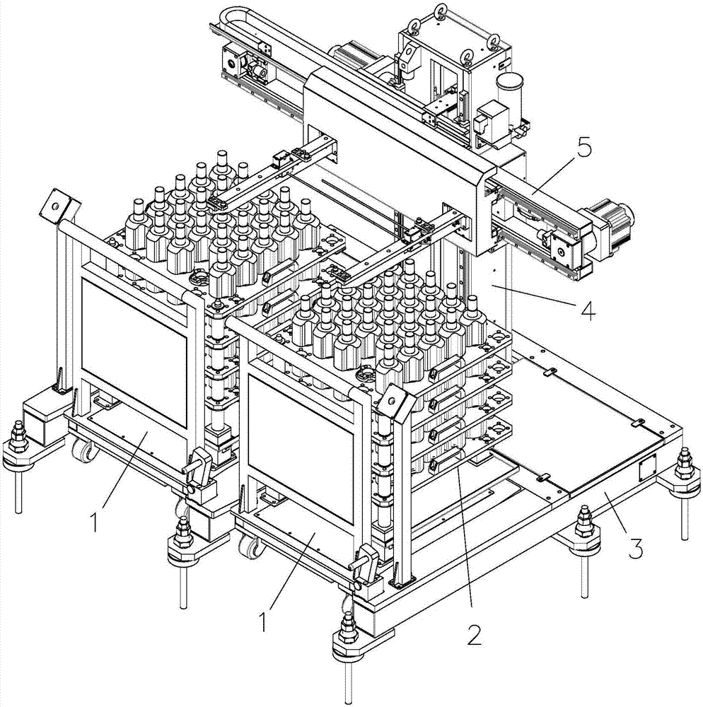
[0029] Such as Figure 1~8 Shown, a kind of stacking type silo, comprises trolley 1, and pallet 2 is placed on the trolley 1, and described silo comprises:

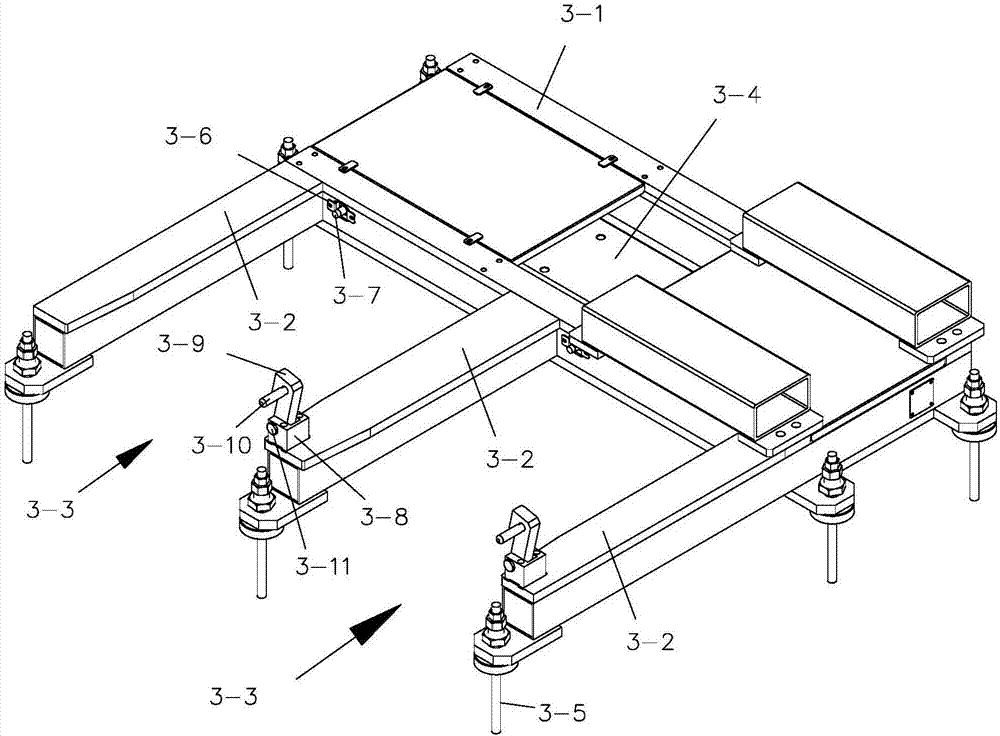
[0030] -The base 3 matched with the trolley 1, the base 3 includes a seat body 3-1, and one side of the seat body 3-1 is provided with 3 limit columns 3-2, and the three limit columns 3-2 connect the seat body Two stacking stations 3-3 are separated on one side of the 3-1, and the base body 3-1 is provided with a mounting groove 3-4, and the surrounding ends of the base body 3-1 and 3 limit columns 3-2 The end is provided with feet 3-5, and two trolleys 1 can enter into two stacking stations 3-3 at the same time, and one of the stacking stations 3-3 is located on the side of the seat body 3-1 The proximity switch 3-7 that is matched with the cart 1 is provided with the proximity swit...


PUM


Abstract

The invention discloses a stacking type stock bin. The stacking type stock bin comprises carts. Trays are placed on the carts. The stock bin comprises a base matched with the carts. The base comprises a base body. One side of the base body is provided with three limiting hurdles. The three limiting hurdles divide one side of the base body into two stacking working positions. An installing groove is formed in the base body. Grounding feet is arranged at the end parts of the periphery of the base body and the end parts of the three limiting hurdles. The two carts can simultaneously enter the two stocking working positions, and one of the two stocking working positions is located at the side edge of the base body and is provided with a proximity switch which is matched with the carts through a proximity switch bracket. The stacking type stock bin is reasonable in structure, low in manufacturing and maintaining costs and simple in operation, meanwhile, workpieces can be stacked by multiple layers, the material storing quantity is high, work blank and finished workpieces can be simultaneously stored, and the workpieces are automatically transferred to the carts.

Description

technical field [0001] The invention relates to a feed bin, in particular to a feed bin for a sliding sleeve processing part. Background technique [0002] In the automatic production line of sliding sleeve processing, it is a relatively cumbersome process to complete the storage, transportation and arrangement of workpiece blanks and finished products; [0003] First of all, storage is more difficult. Sliding sleeve parts are easy to roll, and it is unrealistic to stack them randomly. At the same time, they are easy to damage the parts, and the stacking arrangement lacks suitable placement tools. If they are placed in boxes, the number of parts is difficult to count. Difficult to take, not suitable for the automatic loading and unloading of workpieces by truss manipulators in the later stage; [0004] At the same time, the transportation and arrangement of workpieces is another difficult problem. There are many small and medium-sized enterprises in our country. Such enterp...

Claims


Application Information

Patent Timeline
Patent Type & Authority Applications(China)
IPC IPC(8): B65G60/00B65G57/03B65G59/02B65G47/90B65G1/04
CPCB65G1/0407B65G47/901B65G57/03B65G59/02B65G60/00B65G2201/0258
Inventor 沈金伟陈冬明
Owner 常州市巨人机器人科技有限公司
Why Eureka
Try Eureka