A passive device testing intermodulation device

A passive device and adapter technology, applied in the field of communication, can solve the problems of difficult judgment, time-consuming and laborious cleaning, incomplete cleaning, etc., and achieve the effect of reducing the difficulty of cleaning, facilitating air circulation, and cleaning quickly.

Inactive Publication Date: 2017-12-12
ANHUI LUXUN ELECTRONICS TECH
View PDF6 Cites 2 Cited by
  • Summary
  • Abstract
  • Description
  • Claims
  • Application Information

AI Technical Summary

Problems solved by technology

[0003] During the intermodulation test of passive devices, the mechanical stability of the test cable has a mechanical life of 500 to 1000 times. It needs to be screwed into the connector of the device under test through threads, and the connector should be tightened with a torque of 25 to 30N.m. At the same time, the tightening process is easy. Metal shavings will be generated, which will affect the accuracy of the test indicators. It is necessary to loosen the thread again. After cleaning, tighten it again
[0004] In the prior art, the intermodulation device for passive device testing cannot quickly clean up the metal shavings generated during the intermodulation test, which is not only time-consuming and laborious, but also incomplete; The tightness indication function makes it difficult to judge whether the fit is complete, which affects the accuracy of the intermodulation test data, so a new type of passive device test intermodulation device is urgently needed to solve the above problems

Method used


Image

  • A passive device testing intermodulation device
  • A passive device testing intermodulation device
  • A passive device testing intermodulation device

Examples


Embodiment Construction

[0020] In order to make the technical means, creative features, goals and effects achieved by the present invention easy to understand, the present invention will be further described below in conjunction with specific embodiments.

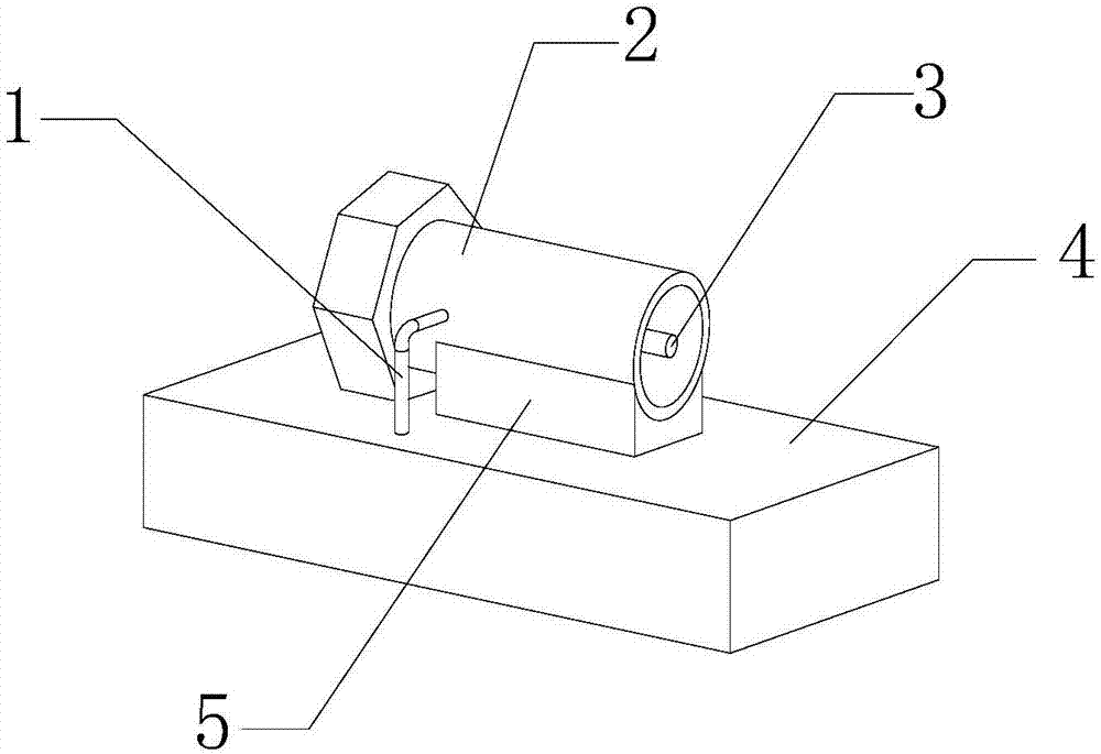
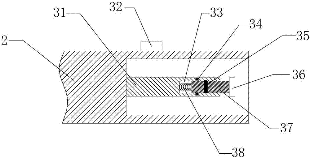
[0021] see Figure 1-Figure 3 , the present invention provides a technical solution: a passive device test intermodulation device, including a device main body, a debris purging mechanism 1 and an in-position indicating mechanism 3, the device main body includes an adapter 2, a bottom box 4 and a support seat 5, The adapter 2 is installed on the upper end surface of the bottom box 4 through the support base 5 .

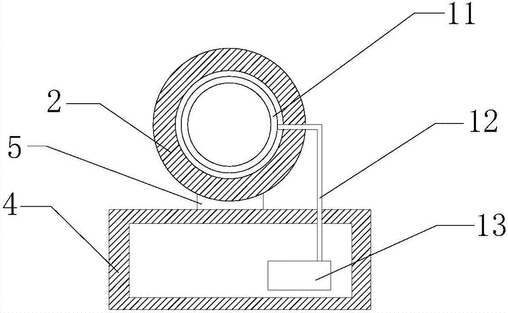
[0022] Debris purging mechanism 1 includes annular pipe 11, connecting pipe 12 and blower 13, blower 13 is arranged inside the bottom box 4, annular pipe 11 is assembled in adapter 2, the upper end of connecting pipe 12 passes through the annular side of adapter 2, and Connect the annular pipe 11, the lower end of the connecting pipe 12 ...


PUM


Abstract

The invention provides a passive device testing intermodulation device comprising an annular pipe, a connecting pipe, an air blower, an indicating lamp, a hollow cavity, a first contact sheet, a second contact sheet, a front conductor sheet, an insulation rod and a spring. The annular pipe is disposed in an adapter; the upper end of the connecting pipe penetrates the annular side surface of the adapter and is connected with the annular pipe; the lower end of the connecting pipe penetrates the upper end face of a bottom box and is connected with the air blower, so that scraps can be cleaned quickly; the indicating lamp is arranged on the annular side surface of the adapter; the right end of the insulation rod is installed on the middle position of the left end surface of the front conductor sheet; the left end of the spring is fixed to the left end surface of the inside of the hollow cavity; the first contact sheet is mounted on the inner wall of the hollow cavity and the second contact sheet is mounted on the annular side surface of the insulation rod. The passive device testing intermodulation device has a location indicating function, and is high in stability and reliability; the passive device testing intermodulation device can clean scraps quickly.

Description

technical field [0001] The invention is an intermodulation device for passive device testing, which belongs to the technical field of communication. Background technique [0002] In the process of communication equipment production and network construction, passive devices exhibit nonlinear characteristics under high power conditions. When carrier signals of multiple frequencies pass through passive components, passive intermodulation interference will occur, thereby affecting the capacity and quality of the system. With the improvement of communication system quality requirements, reducing passive intermodulation interference has become an important consideration for passive devices. [0003] During the intermodulation test of passive devices, the mechanical stability of the test cable has a mechanical life of 500 to 1000 times. It needs to be screwed into the connector of the device under test through threads, and the connector should be tightened with a torque of 25 to 3...

Claims


Application Information

Patent Timeline
Patent Type & Authority Applications(China)
IPC IPC(8): G01R31/00B08B5/02
CPCG01R31/001B08B5/02
Inventor 付玉芹
Owner ANHUI LUXUN ELECTRONICS TECH
Why Eureka
Try Eureka