Refrigeration and separation tank for producing liquefied natural gas

A technology of liquefied natural gas and separation tank, which is applied in separation method, dispersed particle separation, gas fuel and other directions, can solve the problems of affecting the service life of subsequent devices, liquid retention, equipment loss, etc., and achieves good gas-liquid separation effect, convenience and stability Work, improve the effect of service life

Inactive Publication Date: 2017-12-15
JIANGSU ZHUODA INFORMATION TECH CO LTD
View PDF0 Cites 0 Cited by
  • Summary
  • Abstract
  • Description
  • Claims
  • Application Information

AI Technical Summary

Problems solved by technology

[0003] However, in actual operation, when the product contains a large amount of liquid, it is easier to separate gas and liquid; when the product contains only a small amount of liquid and most of it is gas, it is difficult for the traditional separation tank to separate most of the gas. The liquid is retained, and the liquid enters the circulation system with the air flow, and performs heat exchange and compression operations again, which not only wastes energy, but also has a certain loss on subsequent equipment, which affects the service life of subsequent devices

Method used


Image

  • Refrigeration and separation tank for producing liquefied natural gas

Examples


Embodiment 1

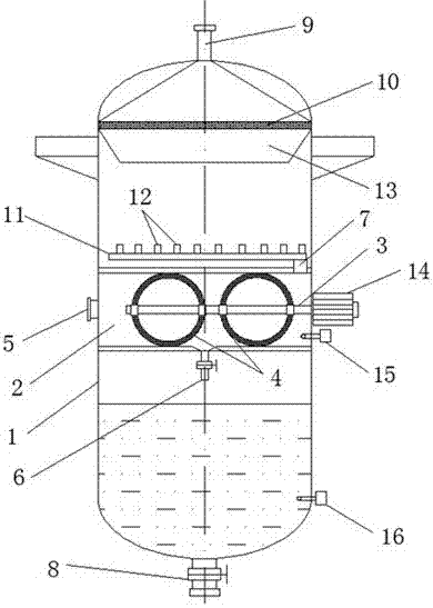
[0015] Embodiment 1: as figure 1 A refrigeration separation tank for the production of liquefied natural gas is shown, the refrigeration separation tank is a cylindrical shell 1, the middle part of the shell 1 is provided with a sealed cylindrical separation tank 2, the separation tank 2 A horizontally installed rotating shaft 3 is provided inside the rotating shaft 3, and a plurality of spherical filtrate screens 4 are arranged on the rotating shaft 3. The diameter of the filtrate screen 4 is the same as the inner diameter of the separation tank 2, and the housing 1 on the side of the separation tank 2 A feed port 5 is provided, a rotating motor 14 is provided on the housing 1 on the other side of the separation tank 2, and the rotating motor 14 is connected to the rotating shaft 3, and an air outlet 7 is provided on the top of the separation tank 2 on one side of the rotating motor 14 , the bottom of the separation tank 2 is provided with a drain port 6, the top of the housi...

Embodiment 2

[0016] Embodiment 2: as figure 1 As shown, the top of the housing 1 is provided with a secondary filtrate screen 10, and the secondary filtrate screen 10 is arranged directly below the tank exhaust port 9, and a conical Deflector 13; under normal circumstances, the gas and liquid have been completely separated in the separation tank 2, but, in order to ensure the separation effect, the filtrate is further carried out through the secondary filtrate screen 10 to prevent the liquid medium from entering the follow-up device with the gas middle.

Embodiment 3

[0017] Embodiment 3: as figure 1 As shown, the top of the separation tank 2 is provided with an air flow distribution pipe 11, and a plurality of vertically upward distribution ports 12 are evenly distributed above the air flow distribution pipe 11, and the air flow distribution pipe 11 is connected to the air outlet 7; The pipe 11 evenly distributes the airflow, which facilitates the airflow to evenly pass through the tank exhaust port 9 and the secondary filtrate screen 10, and the device operates stably and is convenient for separation.


PUM


Abstract

The invention discloses a refrigeration and separation tank for producing liquefied natural gas. The refrigeration and separation tank is a cylindrical shell body, wherein a sealed cylindrical separation groove is formed in the middle of the shell body; a rotary shaft, which is horizontally mounted, is arranged in the separation groove; the rotary shaft is provided with a plurality of spherical liquid filtering screen meshes; the diameter of the liquid filtering screen meshes is the same as the inner diameter of the separation groove; a feeding hole is formed in the shell body at one side of the separation groove and a rotary motor is arranged on the shell body at the other side of the separation groove; the rotary motor is connected onto the rotary shaft; a gas outlet is formed in the top of the separation groove in one side of the rotary motor; a liquid discharging opening is formed in the bottom of the separation groove; a tank body exhausting opening is formed in the top of the shell body; a tank body liquid discharging opening is formed in the bottom of the shell body; the liquid discharging opening is provided with an electromagnetic control valve. The refrigeration and separation tank is improved and a gas product which only contains less liquid and is generated in a liquefied natural gas production process is treated; the device has the advantages of simple structure, convenience for operation, accuracy in controlling and good gas-liquid separation effect and is convenient for subsequent production of the liquefied natural gas.

Description

technical field [0001] The invention relates to the field of production equipment of liquefied natural gas, in particular to a refrigeration separation tank used for the production of liquefied natural gas. Background technique [0002] For the production process of liquefied natural gas, it needs to undergo multiple operations such as heat exchange and compression. After the heat exchanger is operated; under the environment of low temperature and high pressure, the discharged products include gas and partially cooled liquid. During several heat exchange operations, the gas component accounts for the majority, and the liquid only has a small part, and the liquid will be mixed with the gas and enter the subsequent device; therefore, in this process, a separation tank is generally used to separate it . [0003] However, in actual operation, when the product contains a large amount of liquid, it is easier to separate gas and liquid; when the product contains only a small amoun...

Claims


Application Information

Patent Timeline
Patent Type & Authority Applications(China)
IPC IPC(8): B01D46/00B01D46/10C10L3/06
CPCB01D46/0056B01D46/10C10L3/107B01D46/62
Inventor 杨飞孙东东陈泉王涛张雨李纯
Owner JIANGSU ZHUODA INFORMATION TECH CO LTD
Why Eureka
Try Eureka