Spiral detecting machine

A detection machine and detection mechanism technology, which is applied in the field of detection machines, can solve problems such as large differences in detection reference points, large detection error deviations, and backward detection methods, and achieve the effects of fast rotation speed, reduced errors, and stable push effects

Pending Publication Date: 2017-12-15
南京三智视觉科技有限公司
View PDF0 Cites 4 Cited by
  • Summary
  • Abstract
  • Description
  • Claims
  • Application Information

AI Technical Summary

Problems solved by technology

[0002] When detecting the pitch between the spirals on cylindrical materials, projection detection is usually used in the past, manual measurement, the detection means are backward, the detection a...

Method used


Image

  • Spiral detecting machine
  • Spiral detecting machine
  • Spiral detecting machine

Examples


Embodiment

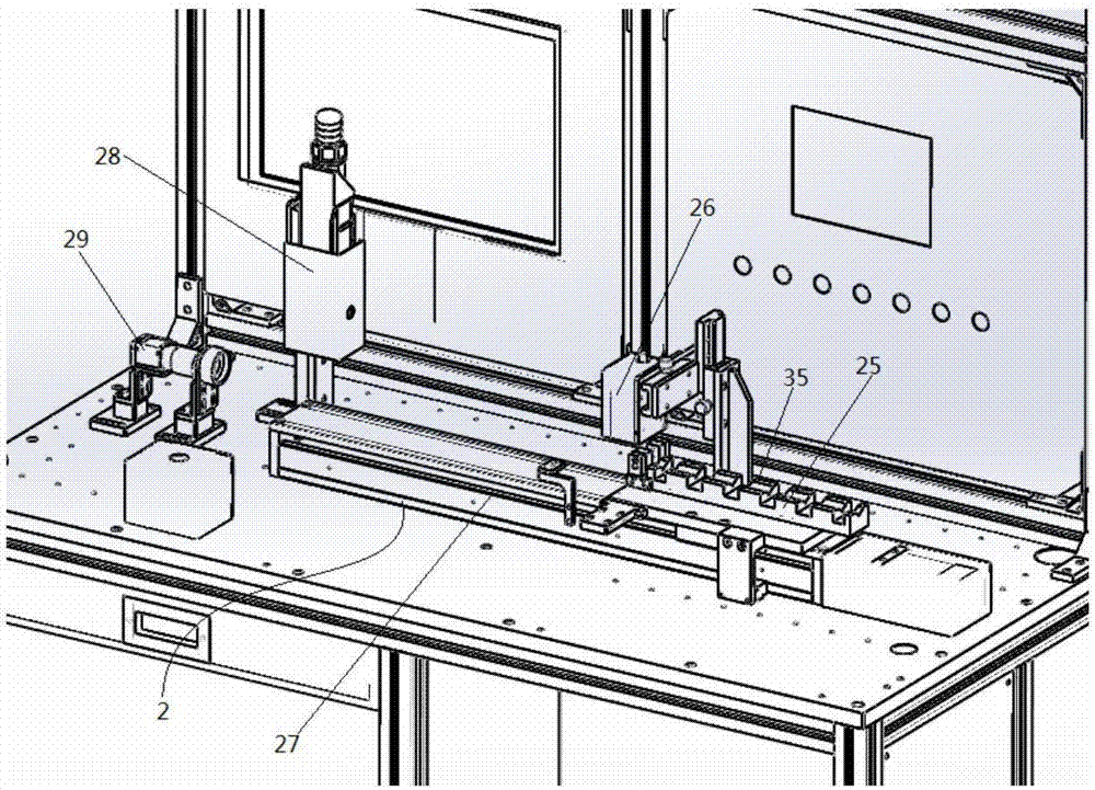
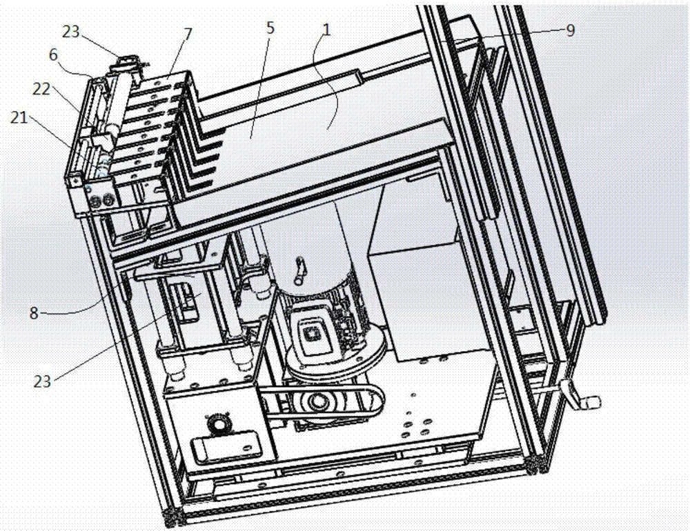
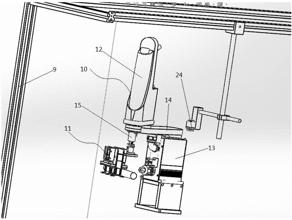
[0031] Such as Figure 1-5As shown, a screw detection machine is disclosed in this embodiment, which includes a feeding mechanism 1, a screw detection mechanism 2, a feeding mechanism 3 and a multi-purpose manipulator mechanism 4 arranged on the top of each mechanism. The feeding mechanism 1 includes a feeding slope 5 and the rotating device 6, the feeding slope 5 and the rotating device 6 are provided with a sliding material slope 7, the feeding slope 5 and the sliding material slope 7 are all inclined towards the rotation device 6, and the height of the feeding slope 5 is lower than the sliding material slope The height of 7, the lowermost part of the feeding slope 5 is provided with a feeding pusher 8, and the feeding pusher 8 can push the material from the feeding slope 5 onto the sliding material slope 7, and the sliding material slope 7 is inclined downward at the lowest point. Rotating device 6; one end of the feeding mechanism 1 is provided with a spiral detection mech...


PUM


Abstract

The invention discloses a spiral detection machine, which includes a feeding mechanism, a spiral detection mechanism, a feeding mechanism and a multi-purpose manipulator mechanism arranged on the upper part of each mechanism. The feeding mechanism includes a feeding slope and a rotating device, a feeding slope and a rotating device A sliding material slope is provided, and a feeding pusher is provided at the lowest point where the feeding slope slopes downward. The feeding pusher can push the material from the feeding slope to the sliding material slope. One end of the material mechanism is provided with a spiral detection mechanism, and one side of the spiral detection mechanism is provided with a blanking mechanism. The material is automatically fed one by one by the feeding mechanism, which is equipped with a rotating device to automatically rotate and position the material, and then the multi-purpose manipulator mechanism automatically transports the material to the screw detection mechanism for automatic detection. Put it into the unloading mechanism, and the unloading mechanism will pack the materials according to the test results.

Description

technical field [0001] The invention relates to the field of detection machines, in particular to a spiral detection machine Background technique [0002] When detecting the pitch between the spirals on cylindrical materials, projection detection was usually used in the past, manual measurement, the detection method is backward, the detection accuracy is low, the detection efficiency is slow, and the detection error deviation is large after the long-term fatigue of the detection personnel. The detection benchmarks vary widely. Contents of the invention [0003] The purpose of the present invention is to overcome the above problems existing in the prior art and provide a spiral detector. The present invention has high degree of automation, accurate measurement method and continuous operation. The materials are automatically fed one by one by the feeding mechanism. A rotating device is installed to automatically rotate and position the material, and then the multi-purpose m...

Claims


Application Information

Patent Timeline
IPC IPC(8): B07C5/34B07C5/02B07C5/36
CPCB07C5/02B07C5/34B07C5/361B07C5/362
Inventor 杨文山
Owner 南京三智视觉科技有限公司
Why Eureka
Try Eureka