
Paper cutting device for printing

A technology of cutting device and printing paper, which is applied in metal processing and other directions, can solve the problems of not being able to manually adjust the length and width of cutting and cutting a large amount of paper at the same time, etc., and achieve the effects of long service life, not easy to deform, and high hardness.

Inactive Publication Date: 2017-12-15
刘慎柱
View PDF8 Cites 2 Cited by
  • Summary
  • Abstract
  • Description
  • Claims
  • Application Information

AI Technical Summary

Problems solved by technology

[0006] In order to overcome the shortcomings in the prior art that the cutting degree of length and width cannot be manually adjusted freely and a large number of papers cannot be cut at the same time, the technical problem to be solved by the present invention is to provide a paper that can manually adjust the cutting degree of length and width freely and can cut a large number of papers Printing paper cutting device that simultaneously cuts paper

Method used


Image

  • Paper cutting device for printing
  • Paper cutting device for printing
  • Paper cutting device for printing

Examples


Embodiment 1

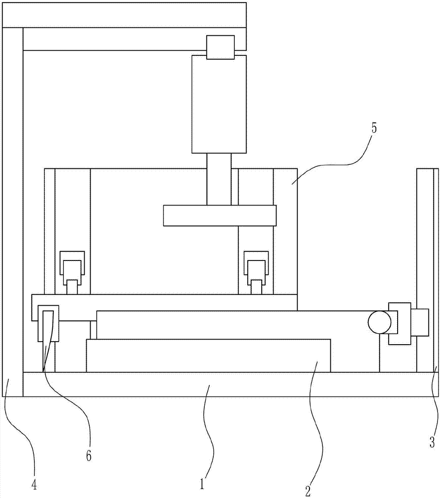
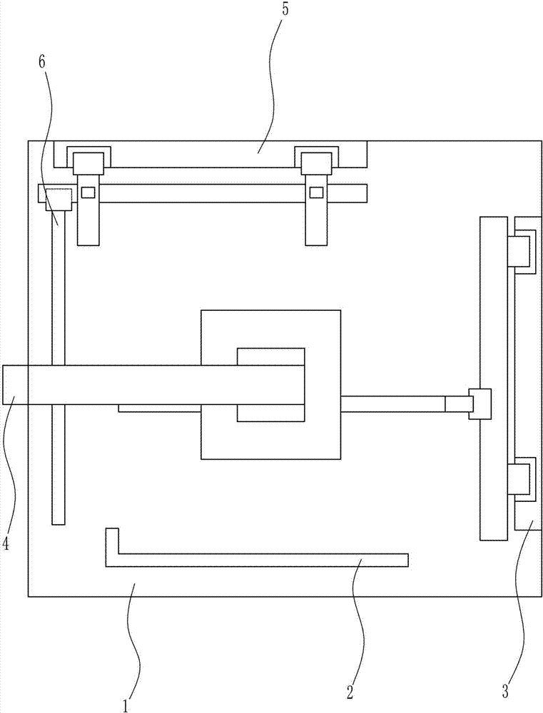
[0031] A printing paper cutting device, such as Figure 1-6 As shown, it includes a bottom plate 1, a baffle plate 2, a fixed plate 3, a pressing mechanism 4, a supporting plate 5 and a cutting mechanism 6, the middle part of the left wall of the bottom plate 1 is connected with a pressing mechanism 4, and the front side of the top of the bottom plate 1 is connected with a baffle plate 2. A fixing plate 3 is connected to the right side of the top of the bottom plate 1 , a supporting plate 5 is connected to the rear side of the top of the bottom plate 1 , and a cutting mechanism 6 is arranged between the supporting plate 5 and the fixing plate 3 .

Embodiment 2

[0033] A printing paper cutting device, such as Figure 1-6 As shown, it includes a bottom plate 1, a baffle plate 2, a fixed plate 3, a pressing mechanism 4, a supporting plate 5 and a cutting mechanism 6, the middle part of the left wall of the bottom plate 1 is connected with a pressing mechanism 4, and the front side of the top of the bottom plate 1 is connected with a baffle plate 2. A fixing plate 3 is connected to the right side of the top of the bottom plate 1 , a supporting plate 5 is connected to the rear side of the top of the bottom plate 1 , and a cutting mechanism 6 is arranged between the supporting plate 5 and the fixing plate 3 .

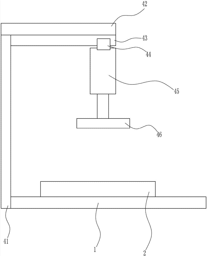
[0034] The pressing mechanism 4 includes a bracket 41, a first connecting rod 42, a first slide rail 43, a first slider 44, an electric push rod 45 and a pressure plate 46. A bracket 41 is connected to the middle of the left wall of the bottom plate 1, and a bracket 41 is connected to the top of the bracket 41. A first connecting ro...

Embodiment 3

[0036] A printing paper cutting device, such as Figure 1-6 As shown, it includes a bottom plate 1, a baffle plate 2, a fixed plate 3, a pressing mechanism 4, a supporting plate 5 and a cutting mechanism 6, the middle part of the left wall of the bottom plate 1 is connected with a pressing mechanism 4, and the front side of the top of the bottom plate 1 is connected with a baffle plate 2. A fixing plate 3 is connected to the right side of the top of the bottom plate 1 , a supporting plate 5 is connected to the rear side of the top of the bottom plate 1 , and a cutting mechanism 6 is arranged between the supporting plate 5 and the fixing plate 3 .

[0037] The pressing mechanism 4 includes a bracket 41, a first connecting rod 42, a first slide rail 43, a first slider 44, an electric push rod 45 and a pressure plate 46. A bracket 41 is connected to the middle of the left wall of the bottom plate 1, and a bracket 41 is connected to the top of the bracket 41. A first connecting ro...


PUM


Abstract

The invention relates to a cutting device, in particular to a paper cutting device for printing. According to the technical purpose to be achieved, the paper cutting device for printing is provided, wherein the length and width cutting degree can be manually adjusted at will, and a large number of pieces of paper can be cut at the same time. In order to achieve the above technical purpose, the paper cutting device for printing is provided and comprises a bottom plate and the like. A pressure applying mechanism is connected to the middle portion of the left wall of the bottom plate; a baffle is connected to the front side of the top of the bottom plate; a fixing plate is connected to the right side of the top of the bottom plate; a supporting plate is connected to the rear side of the top of the bottom plate; and a cutting mechanism is arranged between the supporting plate and the fixing plate. The paper cutting device for printing is designed, an electric push rod can effectively and stably drive the pressing plate to vertically move, and a user can also conveniently conduct pressure applying control over the position needing to be subjected to pressure applying due to left-right movement of the pressing plate.

Description

technical field [0001] The invention relates to a cutting device, in particular to a printing paper cutting device. Background technique [0002] Printing is a process of transferring text, pictures, photos, anti-counterfeiting and other manuscripts to the surface of paper, fabrics, plastics, leather and other materials through plate making, ink application, pressure and other processes to copy the content of the manuscript in batches. Printing paper is the paper used for printing. Commonly used printing papers in China include coated paper, offset paper, trademark paper, kraft paper, corrugated paper, paper bag paper, cellophane, moisture-proof paper, white cardboard, etc. Offset printing requires printing paper to have a smoother surface, better printing performance, and be able to withstand large temperature and moisture changes without curling. Internationally, a series of new varieties of mechanical wood pulp printing paper have been developed from the varieties of pr...

Claims


Application Information

Patent Timeline
Patent Type & Authority Applications(China)
IPC IPC(8): B26D11/00B26D1/08B26D5/08B26D7/00
CPCB26D1/085B26D5/086B26D7/0006B26D11/00B26D2011/005
Inventor 刘慎柱
Owner 刘慎柱
Learn More