
New compound mode applied to compound molding skin

A composite mode and composite molding technology, which is applied in the direction of layered products, lamination devices, lamination, etc., can solve the problems of process edge waste and high ratio, and achieve the effects of cost saving, waste reduction, and high skin compounding efficiency

Inactive Publication Date: 2017-12-15
YANFENG HAINACHUAN AUTOMOTIVE TRIM SYST CO LTD
View PDF7 Cites 0 Cited by
  • Summary
  • Abstract
  • Description
  • Claims
  • Application Information

AI Technical Summary

Problems solved by technology

[0002] Composite molding includes but is not limited to vacuum forming, thermocompression forming, etc.; it is especially suitable for composite modes where the skin is composed of multiple layers, and each layer of material has different functions, while the skin of vacuum forming (including female mold and male mold) is generally TPO layer and The PP foam layer is compounded. When the supplier produces the skin, it uses two layers slightly larger than the supply size (width direction). After compounding, it goes through a cutting process and cuts to the required size. Material supply, when vacuum forming (including female mold and male mold), the skin of the coil or sheet is clamped by hinges or fixtures, heated and then formed by a vacuum composite mold. The appearance of the composite product requires a TPO layer on the front and a foam layer as The foam layer provides a soft texture. The skin cutting process is mainly to cut the skin of the process edge by skin compounding, but the main problem at present is: the process edge cut by the cutting process is a serious waste; except for the mold core They are all non-value-added parts in the production process, and their proportion is relatively high

Method used


Image

  • New compound mode applied to compound molding skin
  • New compound mode applied to compound molding skin
  • New compound mode applied to compound molding skin

Examples


Embodiment Construction

[0022] The following will clearly and completely describe the technical solutions in the embodiments of the present invention with reference to the accompanying drawings in the embodiments of the present invention. Obviously, the described embodiments are only some, not all, embodiments of the present invention.

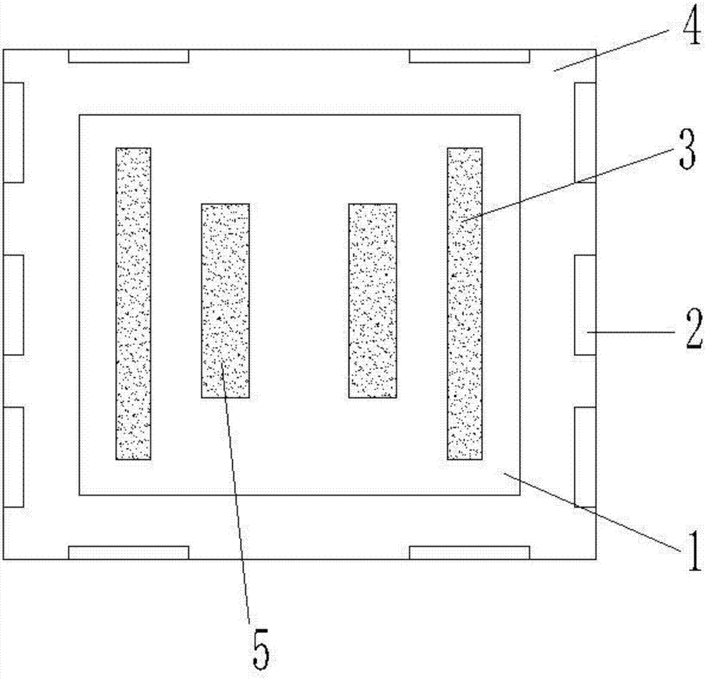
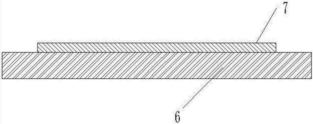
[0023] refer to Figure 1-3 , a new composite mode applied to the composite molding skin, including a skin module 4, the skin module 4 includes a clamping module 2, a mold cavity module 1, a base material skeleton module, a PP foam layer 6 and a TPO layer 7, and The base material skeleton module includes a mold first core module 3 and a mold second core module 5, the number of clamp clamp modules 2 is eight to ten, and eight to ten clamp clamp modules 2 are equidistantly distributed in Around the outer wall of one side of the skin module 4, the quantity of the first core module 3 of the mold and the quantity of the second core module 5 of the mold are two to six, and...


PUM


Abstract

The invention discloses a new compound mode applied to compound molding skin. The new compound mode comprises a skin module which comprises eight to ten clamp clamping modules, a mould cavity module, a substrate skeleton module, a PP foam layer and a TPO layer, the substrate skeleton module comprises two to six first mould core modules and two to six second mould core modules, and the eight to ten clamp clamping modules are uniformly distributed on the periphery of the outer wall on one side of the skin module at equal intervals. In the new compound mode, the TPO layer meets the appearance surface of a product substrate, the PP foam layer meets the requirements of the molding process and the size of the technology edge, in the production of compound layers different in size, the fluctuation of the PP foam layer and the TPO layer in the skin production process is allowed, the waste problem that the skin is cut away in the skin production process is avoided, the material utilization rate is improved, and energy conservation and consumption reduction are achieved.

Description

technical field [0001] The invention relates to the technical field of composite molding skins, in particular to a novel composite mode applied to composite molding skins. Background technique [0002] Composite molding includes but is not limited to vacuum forming, thermocompression forming, etc.; it is especially suitable for composite modes where the skin is composed of multiple layers, and each layer of material has different functions, while the skin of vacuum forming (including female mold and male mold) is generally TPO layer and The PP foam layer is compounded. When the supplier produces the skin, it uses two layers slightly larger than the supply size (width direction). After compounding, it goes through a cutting process and cuts to the required size. Material supply, when vacuum forming (including female mold and male mold), the skin of the coil or sheet is clamped by hinges or fixtures, heated and then formed by a vacuum composite mold. The appearance of the comp...

Claims


Application Information

Patent Timeline
Patent Type & Authority Applications(China)
IPC IPC(8): B32B37/06B32B37/00
CPCB32B37/06B32B37/00
Inventor 边灿孙天明
Owner YANFENG HAINACHUAN AUTOMOTIVE TRIM SYST CO LTD
Learn More