Pay-off rack and cable manufacturing equipment

A technology for manufacturing equipment and pay-off racks, used in cable/conductor manufacturing, electrical components, transporting filamentous materials, etc., and can solve problems such as collision, component collision, equipment damage, etc.

Inactive Publication Date: 2017-12-15
SHENZHEN HUAHU TECH CO LTD
View PDF0 Cites 3 Cited by
  • Summary
  • Abstract
  • Description
  • Claims
  • Application Information

AI Technical Summary

Problems solved by technology

[0003] However, the tray of the existing pay-off frame is only connected to the lifting mechanism by four steel wires, and the lifting block is not completely positio

Method used


Image

  • Pay-off rack and cable manufacturing equipment
  • Pay-off rack and cable manufacturing equipment

Examples


Example Embodiment

[0021] The core of the present invention is to provide a pay-off stand, which can prevent the lifting block from rotating horizontally. Another core of the present invention is to provide a cable manufacturing equipment including the above-mentioned pay-off frame, which can prevent the lifting block from rotating horizontally and avoid equipment damage.

[0022] In order to make those skilled in the art better understand the solution of the present invention, the present invention will be further described in detail below with reference to the accompanying drawings and specific embodiments.

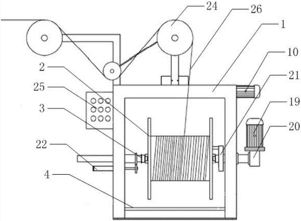
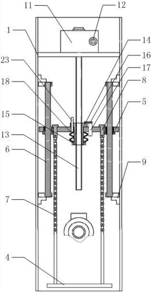
[0023] Please refer to figure 1 and figure 2 , figure 1 It is a schematic front view of a specific embodiment of the pay-off rack provided by the present invention; figure 2 It is a schematic side view of a specific embodiment of the pay-off rack provided by the present invention.

[0024] The pay-off rack provided by the specific embodiment of the present invention includes a frame...


PUM


Abstract

The invention discloses a pay-off frame and cable manufacturing equipment. The pay-off frame includes a frame, a bundle tube coil wound with bundle tubes, a thimble mounted on the frame and capable of clamping the bundle tube coil, A pallet for placing the bundle tube tray and a lifting device for lifting the pallet, the lifting device includes a horizontally arranged lifting block and a driver for lifting the lifting block, and the lifting block is located on the pallet and connect the two ends of the tray through connecting pieces, the two sides of the frame are respectively fixed with a vertical optical axis, and the lifting block is sleeved on the optical axis and can move along the optical axis. During the vertical movement of the lifting block, the vertical optical axis makes the up and down strokes have a fixed track, prevents horizontal rotation, avoids equipment damage, and improves equipment stability. The invention also discloses a cable manufacturing equipment comprising the above-mentioned pay-off frame.

Description

technical field [0001] The invention relates to the field of cable manufacturing, in particular to a pay-off frame and cable manufacturing equipment. Background technique [0002] In the manufacturing process of optical cables and cables, multiple pay-off racks are required to implement the pay-off of each sub-unit. The pay-off rack is provided with a bundle tube disk, and the bundle tube used for manufacturing cables is wound on the bundle tube disk. By rotating the bundle tube The disk realizes the wire release. In order to load the bundle tube reel on the pay-off rack, it is necessary to place the bundle tube reel on the pallet, and lift the pallet with the bundle tube reel through the lifting mechanism, so that the bundle tube reel is lifted to a preset height for loading on the pay-off rack . [0003] However, the tray of the existing pay-off frame is only connected to the lifting mechanism by four steel wires, and the lifting block is not completely positioned. Durin...

Claims


Application Information

Patent Timeline
IPC IPC(8): B65H49/32B65H49/18H01B13/00
CPCB65H49/324B65H49/18B65H2701/341H01B13/00
Inventor 邓欢欢
Owner SHENZHEN HUAHU TECH CO LTD
Why Eureka
Try Eureka