Strip-shaped reinforced joint for connection of H-shaped steel beam and short edge of wide steel pipe concrete column

A technology of steel tube concrete columns and H-shaped steel, which is applied in the direction of construction and building construction, and can solve the problems that the cross section of steel columns cannot be too small, the cross section of steel columns cannot be too large, and the use of diaphragms cannot be used, so as to achieve simple node structure processing , good stiffness and strength, and the effect of improving the stress state

Active Publication Date: 2017-12-15
HANGZHOU TONGMSK DESIGN CO LTD
View PDF12 Cites 5 Cited by
  • Summary
  • Abstract
  • Description
  • Claims
  • Application Information

AI Technical Summary

Problems solved by technology

However, due to the small size of the short side of the wide steel pipe concrete column, in order to ensure the smooth pouring of the internal concrete, the diaphragm cannot be installed in the node area, so the connection with the steel beam cannot be in the form of a diaphragm
[0005] Based o

Method used


Image

  • Strip-shaped reinforced joint for connection of H-shaped steel beam and short edge of wide steel pipe concrete column
  • Strip-shaped reinforced joint for connection of H-shaped steel beam and short edge of wide steel pipe concrete column
  • Strip-shaped reinforced joint for connection of H-shaped steel beam and short edge of wide steel pipe concrete column

Examples


Embodiment 1

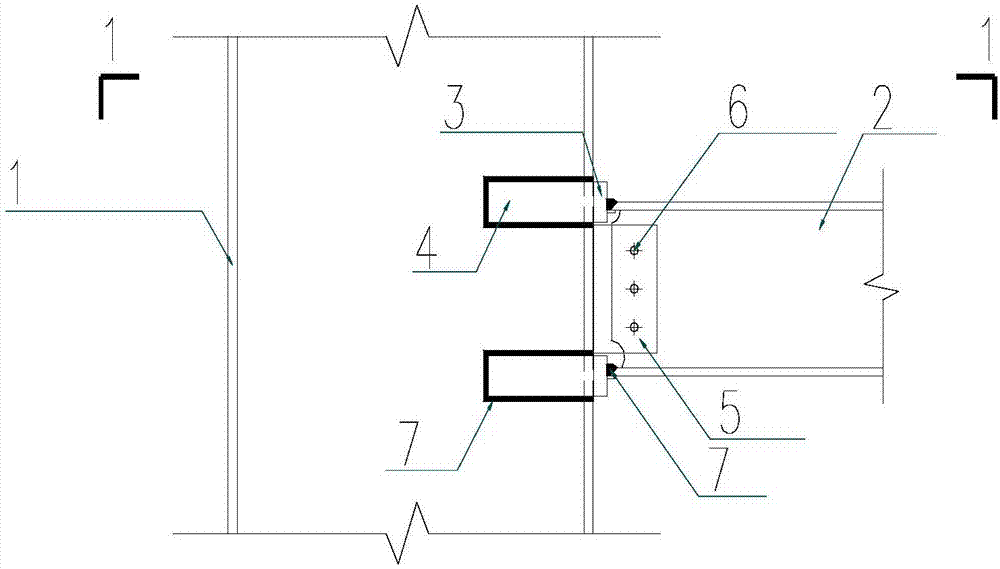
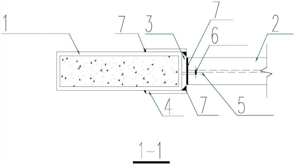
[0046] Such as figure 1 and figure 2 As shown, the embodiment includes: a wide steel pipe concrete column 1, an H-shaped steel beam 2, a strip-shaped reinforcing plate 3, a sticking plate 4, a connecting plate 5 and a high-strength bolt 6.

[0047] The wide steel pipe concrete column 1 is formed by pouring concrete inside a rectangular steel pipe, and the ratio of the long side to the short side of the rectangular steel pipe is 1-4.

[0048] Only one steel beam is rigidly connected to the short side of the wide concrete-filled steel tube column, and two belt-shaped reinforcement plates 3 are fixed on the side where the short side of the wide steel-filled steel tube concrete column 1 is located. The two belt-shaped reinforcement plates 3 correspond to the H-shaped The upper and lower flanges of the steel beam 2, and the end faces of the upper and lower flanges of the H-shaped steel beam 2 are welded to the respective belt-shaped reinforcement plates 3, and the two horizontal ...

Embodiment 2

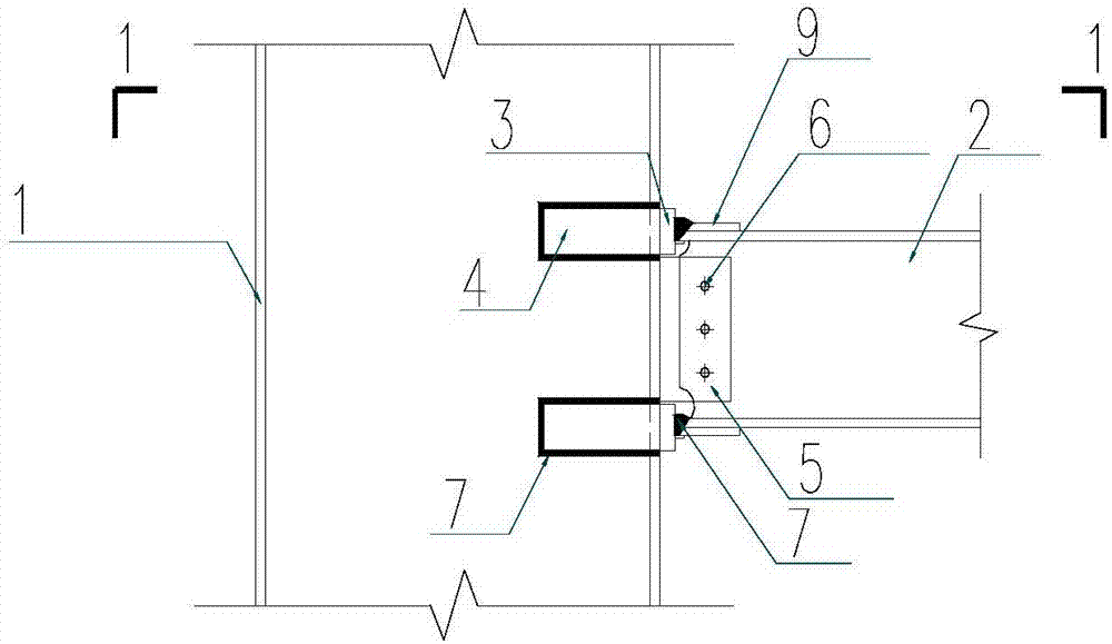
[0055] Such as image 3 and Figure 4 As shown, the present embodiment is based on Embodiment 1, and the upper and lower flanges of the H-shaped steel beam 2 are provided with cover plates 9, and the two cover plates 9 are respectively tightly attached to and welded to the H-shaped steel beam 2, On the surface of the lower flange, the ends of the two cover plates 9 are welded to the respective corresponding strip reinforcement plates 3 .

Embodiment 3

[0057] Such as Figure 5 and Figure 6 As shown, the embodiment includes: wide concrete-filled steel tube column 1 , H-shaped steel beam 2 , belt-shaped reinforcing plate 3 , pasting plate 4 , connecting plate 5 , inserting plate 8 and high-strength bolt 6 .

[0058] The wide steel pipe concrete column 1 is formed by pouring concrete inside a rectangular steel pipe, and the ratio of the long side to the short side of the rectangular steel pipe is 1-4.

[0059] Only one steel beam is rigidly connected to the short side of the wide concrete-filled steel tube column, and two belt-shaped reinforcement plates 3 are fixed on the side where the short side of the wide steel-filled steel tube concrete column 1 is located. The two belt-shaped reinforcement plates 3 correspond to the H-shaped The upper and lower flanges of the steel beam 2, and the end faces of the upper and lower flanges of the H-shaped steel beam 2 are welded to the respective belt-shaped reinforcement plates 3, and t...


PUM


Abstract

The invention discloses a strip-shaped reinforced joint for connection of an H-shaped steel beam and the short edge of a wide steel pipe concrete column. A flange of the H-shaped steel beam is rigidly connected to the side face of the wide steel pipe concrete column through strip-shaped reinforcing plates; a web plate of the H-shaped steel beam is rigidly connected to the side face of the wide steel pipe concrete column through combination of a connecting plate and high-strength bolts; the web plate of the H-shaped steel beam is connected with one end of the connecting plate through the high-strength bolts, and the other end of the connecting plate is welded to the side face where the short edge of the wide steel pipe concrete column is located; the end faces of the flange of the H-shaped steel beam are welded to the strip-shaped reinforcing plates; the strip-shaped reinforcing plates are closely attached and fixed to the side face where the short edge or the long edge of the wide steel pipe concrete column is located; and an inserting plate penetrating through the wide steel pipe concrete column is connected between the two strip-shaped reinforcing plates arranged on the opposite side faces of the wide steel pipe concrete column. The strip-shaped reinforced joint is easy to construct and machine and effective, machining and manufacturing difficulty is reduced, the rigidity and strength of the joint and a joint area are guaranteed, and it is guaranteed that concrete in a pipe has the good pouring quality.

Description

technical field [0001] The invention relates to a belt-shaped reinforced joint used for connecting H-shaped steel beams and short sides of wide steel-filled concrete columns, which can be widely used in the rigid connection between H-shaped steel beams and the short sides of wide steel-filled concrete columns in multi-high-rise steel structures . Background technique [0002] In the multi-story steel structure, the steel beams are mostly H-shaped steel beams, and the steel columns are mostly rectangular wide concrete-filled steel tube columns. The rigid connection of steel beams and steel columns is the most basic measure to provide the overall rigidity and seismic performance of the structure. At present, the commonly used rigid connection is to set a transverse diaphragm at the position corresponding to the beam flange of the steel column, and the internal force of the steel beam flange is transmitted to the steel column through the diaphragm, thus forming a rigid connect...

Claims


Application Information

Patent Timeline
IPC IPC(8): E04B1/58E04B1/30
CPCE04B1/185E04B1/30
Inventor 王彦超付波周耀彬景亭陈杭滨徐永斌
Owner HANGZHOU TONGMSK DESIGN CO LTD
Why Eureka
Try Eureka