Optical cable peeling device

A technology of optical cable and guide wheel, applied in the field of optical cable stripping device, can solve the problems of low stripping efficiency, slow stripping speed, instability, etc., and achieve the effect of ensuring stripping efficiency and quality

Active Publication Date: 2017-12-15
德阳汇川科技有限公司
View PDF10 Cites 4 Cited by
  • Summary
  • Abstract
  • Description
  • Claims
  • Application Information

AI Technical Summary

Problems solved by technology

[0007] The technical problem to be solved by the present invention is that the existing optical cable or cable stripping device has a slow stripping speed and is unstable, and is often used for small batch stripping, and the stripping efficiency is low. Fast speed and stable stripping, suitable for batch stripping of ordinary optical cables by optical cable manufacturers

Method used


Image

  • Optical cable peeling device
  • Optical cable peeling device
  • Optical cable peeling device

Examples


Embodiment 1

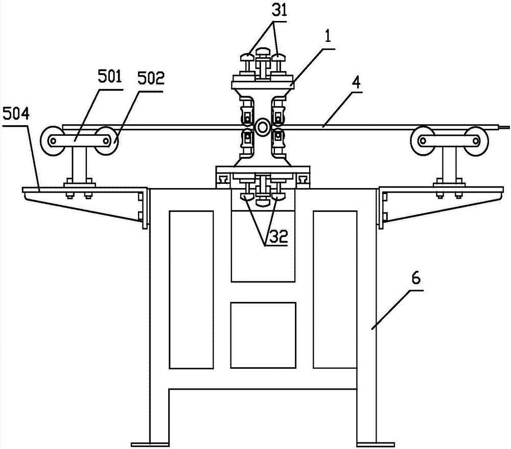
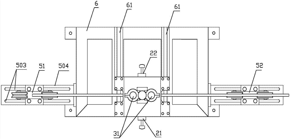
[0056] Such as Figure 1-9 As shown, the present invention provides a kind of optical cable stripping device, comprises frame 6 and machine head 1, and described machine head 1 is fixed on the frame 6, and machine head 1 comprises the side plate 11 that two board faces are oppositely arranged, and The top plate 12 and the bottom plate 13 connected with the two side plates 11 form a frame structure with a rectangular cross section. Correspondingly be provided with front cutter head 21 and rear cutter head 22 on two side plates 11, all be provided with blade 201 on front cutter head 21 and rear cutter head 22, the blade 201 on the front cutter head 21 and rear cutter head 22 is positioned at two sides. Between the two side plates 11 and the blades on the blade 201 are located on a horizontal line facing each other. The top plate 12 is provided with an upper guide wheel set 31, the bottom plate 13 is provided with a lower guide wheel set 32, and the upper guide wheel set 31 and ...

Embodiment 2

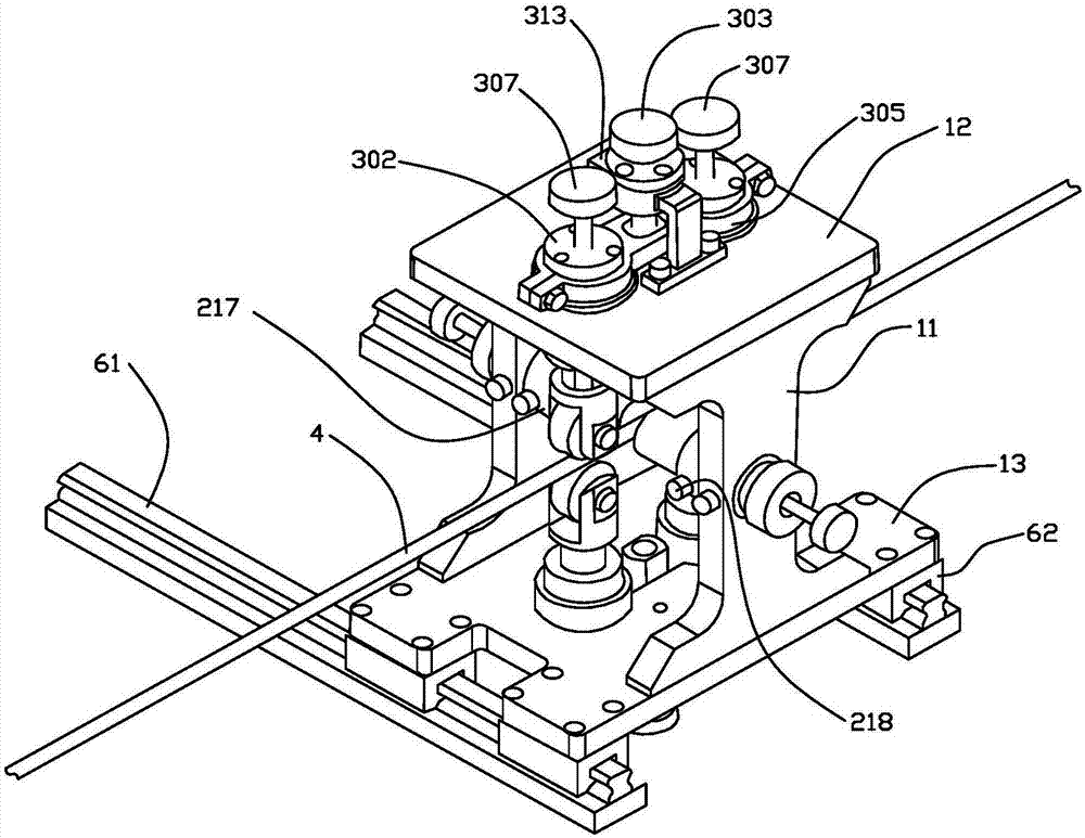
[0058] Further improvement on the basis of Embodiment 1, the front cutter head 21 and the rear cutter head 22 have the same structure, and both include a positioning sliding sleeve 202 arranged on the side plate 11, and a through hole is opened on the side plate 11, and a through hole is formed in the through hole. The cutter head cover 217 is installed on the top, and the positioning sliding sleeve 202 is fixedly inserted in the cutter head cover 217 and fixed by the bolt 218. A cutter body 203 , a cutter body connecting nut 204 and an adjusting screw shaft 205 are sequentially provided in the positioning sliding sleeve 202 along the axial direction. A mounting groove 206 is provided in the cutter body 203, and the mounting groove 206 is used to accommodate the blade 201 and extends along the long axis direction of the cutter body 203; the adjusting screw shaft 205 is provided with a through hole 207 extending in the axial direction, and the through hole 207 A limit screw 208...

Embodiment 3

[0062] Further improvement on the basis of Embodiment 2, the upper guide wheel set 31 and the lower guide wheel set 32 ​​have the same structure, and both include two columnar connecting parts 302 correspondingly penetrating through the top plate 12 and the bottom plate 13, and the columnar connecting parts 302 include The sliding sleeve 306 and the spring adjusting screw rod 307 are provided with through holes on the top plate 12 and the bottom plate 13, the through holes are covered with a copper sleeve, and the sliding sleeve 306 is sleeved in the copper sleeve. The sliding sleeve 306 includes a first through hole 308 and a second through hole 309 in the axial direction, the inner diameter of the first through hole 308 is smaller than the inner diameter of the second through hole 309, the side wall of the spring adjustment screw 307 is threaded with the first through hole 308 connected, and the end of the spring adjusting screw 307 screwed into the sliding sleeve 306 is prov...


PUM


Abstract

The invention discloses an optical cable peeling device which comprises a head, the head comprises two opposite side plates and a top plate and a bottom plate, wherein the top plate and the bottom plate are connected with the two side plates; a front cutting head and a rear cutting head are correspondingly arranged on the two side plates, blades are arranged on the front cutting head and a rear cutting head, and the blades on the front cutting head and the rear cutting head are arranged between the two side plates and opposite with each other; an upper guide wheel set is arranged on the top plate, a lower guide wheel set is arranged on the bottom plate, two sets of guide wheels are arranged on each of the upper guide wheel set and the lower guide wheel set, the two sets of guide wheels are respectively arranged on two sides of the blades, and the two sets of guide wheels of the upper guide wheel set and the two sets of guide wheels of the lower guide wheel set are correspondingly arranged in a line; and the optical cable moves between the two sets of guide wheels of the upper guide wheel set and the two sets of guide wheels of the lower guide wheel set. According to the invention, optical cable production equipment can be utilized to perform mechanical traction, the speed is fast, the peeling is stable, and the device is suitable for an optical cable manufacturer to peel common optical cables in batch.

Description

technical field [0001] The invention relates to an electric power auxiliary device, in particular to an optical cable stripping device. Background technique [0002] Ordinary optical cables are mainly divided into central bundle tube optical cables and layer stranded optical cables from the structure. Ordinary optical cables mainly include: central strength member, possible cushion, PBT loose tube (tube contains multiple optical fibers), fiber paste, cable paste , Composite strip (steel or aluminum), PE outer sheath. After the optical cable is produced, it is wound on the reel, and the length generally ranges from 2km to 3km; the outer diameter of the optical cable is 6mm to 16mm. [0003] Various abnormal problems will inevitably occur during the production process of optical cables, such as: [0004] 1) The attenuation index of the optical fiber in the optical cable is unqualified, and the adjustment process needs to be re-sheathed. [0005] 2) If the appearance or size...

Claims


Application Information

Patent Timeline
Patent Type & Authority Applications(China)
IPC IPC(8): G02B6/44
CPCG02B6/566
Inventor 黎明陈鹏陈曲杨卫东彭林朱维彬
Owner 德阳汇川科技有限公司
Why Eureka
Try Eureka