
Display panel

A technology for display panels and substrates, applied in the directions of optics, instruments, electrical components, etc., can solve problems such as glass substrate cracking and damage, and achieve the effect of preventing crack damage and good support protection

Inactive Publication Date: 2017-12-15
WUHAN CHINA STAR OPTOELECTRONICS SEMICON DISPLAY TECH CO LTD
View PDF4 Cites 7 Cited by
  • Summary
  • Abstract
  • Description
  • Claims
  • Application Information

AI Technical Summary

Problems solved by technology

[0006] The purpose of the present invention is to provide a display panel that can prevent the corresponding glass substrate from cracking and damage; to solve the problem that the corresponding glass substrate is relatively prone to cracking and damage during the handling, transportation or reliability testing of the existing display panel question

Method used


Image

  • Display panel
  • Display panel
  • Display panel

Examples


Embodiment Construction

[0035] The following will clearly and completely describe the technical solutions in the embodiments of the present invention in conjunction with the accompanying drawings in the embodiments of the present invention. Obviously, the described embodiments are only some of the embodiments of the present invention, not all of them. Based on the embodiments of the present invention, all other embodiments obtained by persons of ordinary skill in the art without making creative efforts belong to the protection scope of the present invention.

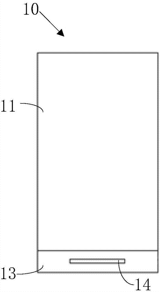
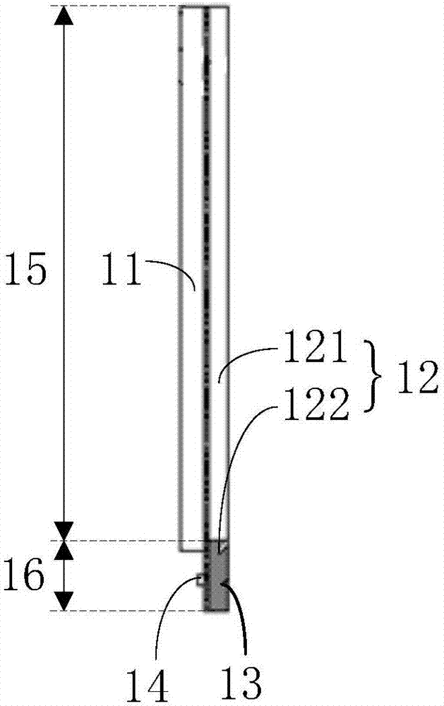
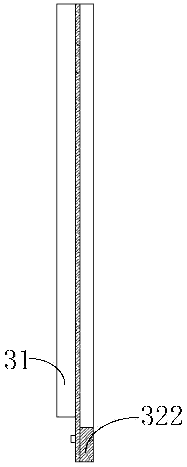
[0036] Please refer to figure 1 and figure 2 , figure 1 It is a top view of a preferred embodiment of the display panel of the present invention; figure 2 It is a side view of the first preferred embodiment of the display panel of the present invention. The display panel 10 of this preferred embodiment includes a first substrate 11, an array substrate, and a light-emitting display layer (not shown in the figure) disposed between the first ...


PUM

PropertyMeasurementUnit
thicknessaaaaaaaaaa
thicknessaaaaaaaaaa

Abstract

The invention provides a display panel. The display panel comprises a first substrate, an array substrate and a luminous display layer; the array substrate comprises a base layer and a plastic base material layer which is arranged on the base layer and used for arranging a pixel unit and driving a chip; the array substrate comprises a display area corresponding to the first substrate and a driving area arranged at one side of the display area; the base layer of the array substrate of the display area is a glass substrate, and the base layer of the array substrate of the diving area is a reinforcement plate. According to the display panel, by means of the reinforcement plate, the array substrate of the area corresponding to a driving chip can be subjected to good support protection, and then the phenomenon that the glass substrate of the display panel is broken and damaged is prevented.

Description

technical field [0001] The present invention relates to the field of display technology, in particular to a display panel. Background technique [0002] With the continuous development of display technology and the continuous improvement of user requirements for display devices, display devices in various electronic devices tend to have narrower borders and thinner thicknesses. [0003] However, as the frame of the display panel of the display device becomes narrower and the thickness of the display panel becomes smaller, the reliability of the display panel of the display device also decreases, for example, problems such as cracking and damage are prone to occur. [0004] Especially in the driver chip setting area of ​​the display panel, since the driver chip of the display panel is usually directly arranged on the corresponding glass substrate by means of COG (Chip On Glass), and the glass substrate corresponding to the driver chip is generally set on a single-layer board,...

Claims


Application Information

Patent Timeline
Patent Type & Authority Applications(China)
IPC IPC(8): G02F1/1333H01L27/32
CPCG02F1/1333H10K59/10
Inventor 陈俊
Owner WUHAN CHINA STAR OPTOELECTRONICS SEMICON DISPLAY TECH CO LTD
Learn More