
Disc type motor rotor structure and disc type motor

A disc motor and rotor structure technology, applied in the direction of magnetic circuit shape/style/structure, electrical components, electromechanical devices, etc., can solve the problems of magnet damage, adhesive failure rotor, unable to meet the needs of mass production, etc.

Inactive Publication Date: 2017-12-15
仪坤动力科技(上海)有限公司
View PDF7 Cites 4 Cited by
  • Summary
  • Abstract
  • Description
  • Claims
  • Application Information

AI Technical Summary

Problems solved by technology

[0002] The disc motor has a high torque density and has broad application prospects. The rotor structure of the disc motor can be divided into a support disc and a permanent magnet steel. The rotor support disc is used as the installation support of the permanent magnet. In the prior art, the permanent magnet The steel is fixed on the rotor disk by bonding or screw fastening. When the motor works for a long time, the rotor will generate magnetic loss and generate heat. If the bonding method is adopted, the bonding may fail and the rotor will fall off; if the direct fixing method is used, it will cause Destroy the structure of the magnet to form damage and affect the magnetic circuit
[0003] The existing technical document "Disc Motor Rotor" (Patent No.: 201210049459.1) discloses an installation method in which permanent magnet steel is fixed in the dovetail groove by pressing blocks after processing the dovetail groove on the rotor disk, which can solve the problem of The lack of traditional magnetic steel fixing, but this installation method needs to use a large number of screws to fix the pressing block, the process is complicated, the processing volume is large, and the cost is high, which cannot meet the needs of mass production

Method used


Image

  • Disc type motor rotor structure and disc type motor
  • Disc type motor rotor structure and disc type motor
  • Disc type motor rotor structure and disc type motor

Examples


Embodiment Construction

[0030] The following will clearly and completely describe the technical solutions in the embodiments of the present invention with reference to the accompanying drawings in the embodiments of the present invention. Obviously, the described embodiments are only part of the embodiments of the present invention, not all of them. Based on the embodiments of the present invention, all other embodiments obtained by persons of ordinary skill in the art without creative efforts fall within the protection scope of the present invention.

[0031] It should be noted that if there is a directional indication (such as up, down, left, right, front, back...) in the embodiment of the present invention, the directional indication is only used to explain the position in a certain posture (as shown in the accompanying drawing). If the specific posture changes, the directional indication will also change accordingly.

[0032] In addition, if there are descriptions involving "first", "second" and ...


PUM


Abstract

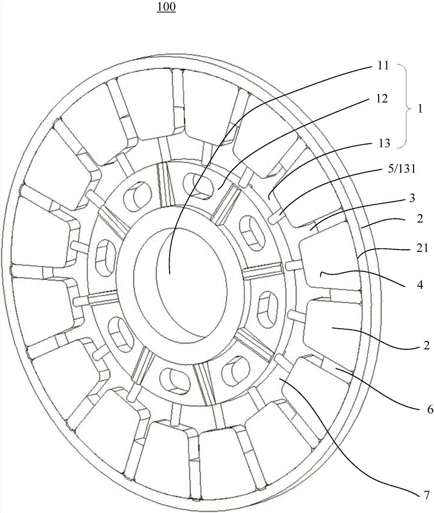
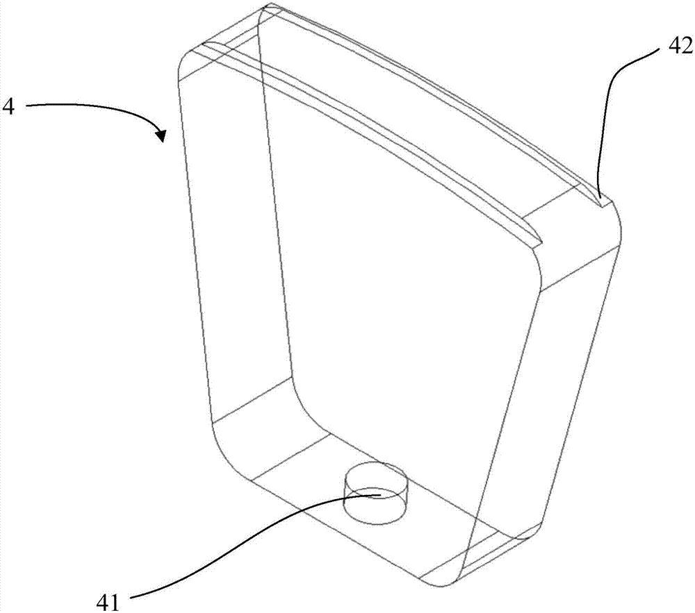
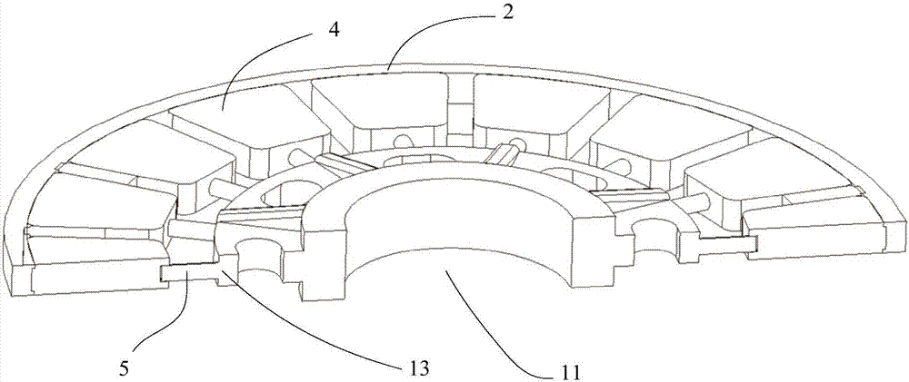
The invention discloses a disc type motor rotor structure and a disc type motor. The disc type motor rotor structure comprises a hub support, an annular clamp and a plurality of permanent magnets, wherein the hub support is in a disc shape, an axle hole is formed in the center of the hub support, an inner limiting ring is installed on the installation face of the hub support and located on the periphery of the axle hole in a protruding mode, the annular clamp is arranged on the periphery of the hub support, a plurality of clamping grooves distributed in the peripheral direction of the annular clamp are formed in the inner side face of the annular clamp, the outer ends of the permanent magnets are correspondingly clamped and limited to the multiple clamping grooves, and the inner ends of the permanent magnets are limited by the inner limiting ring. Due to the fixing structure, the magnetic faces of the permanent magnets are not damaged, the magnetism of the whole magnet is not affected, the structure is simple and convenient to install, the permanent magnets adopt the boltless fixing structure, and the disc type motor rotor structure is suitable for batched production.

Description

technical field [0001] The invention relates to the technical field of motors, in particular to a disc motor rotor structure and the disc motor. Background technique [0002] The disc motor has a high torque density and has broad application prospects. The rotor structure of the disc motor can be divided into a support disc and a permanent magnet steel. The rotor support disc is used as the installation support of the permanent magnet. In the prior art, the permanent magnet The steel is fixed on the rotor disk by bonding or screw fastening. When the motor works for a long time, the rotor will generate magnetic loss and generate heat. If the bonding method is adopted, the bonding may fail and the rotor will fall off; if the direct fixing method is used, it will cause Destroying the structure of the magnet causes damage and affects the magnetic circuit. [0003] The existing technical document "Disc Motor Rotor" (Patent No.: 201210049459.1) discloses an installation method in...

Claims


Application Information

Patent Timeline
IPC IPC(8): H02K1/27
CPCH02K1/2706
Inventor 张景程焦伟
Owner 仪坤动力科技(上海)有限公司
Learn More