Middle pipe with annular groove structure and process for mounting middle pipe ball bearing

An annular groove, ball bearing technology, applied in the direction of rigid brackets, bearing components, shafts and bearings of bearing components, can solve problems such as large influence of concentricity, multiple production equipment, and reduced fan life, to avoid supporting area Too small, improve the assembly yield, reduce the effect of insufficient concentricity

Pending Publication Date: 2021-04-20
东莞市鸿盈电子科技有限公司
View PDF0 Cites 0 Cited by
  • Summary
  • Abstract
  • Description
  • Claims
  • Application Information

AI Technical Summary

Problems solved by technology

Using adhesive bonding and fixing technology, firstly, a layer of adhesive is applied on the inner surface of the middle tube, and then the ball bearing is installed inside the middle tube, and the ball bearing is fixed inside the middle tube by the adhesive, however Using the above assembly method, the adhesive may pass through the dust cover on the ball bearing and enter the interior of the ball bearing, which will reduce the life of the fan or cause the fan to fail
Using the assembly process of interference fit, first of all, the realization of interference fit requires more production equipment, the assembly is more complicated, and the production cost is higher. Then, the concentricity of the upper and lower ball bearings after assembly is greatly affected by the middle tube. , concentricity is difficult to guarantee
[0004] The assembly process of the above two structures can no longer meet the market's fixed demand for ball bearings in high-speed fans

Method used


Image

  • Middle pipe with annular groove structure and process for mounting middle pipe ball bearing
  • Middle pipe with annular groove structure and process for mounting middle pipe ball bearing
  • Middle pipe with annular groove structure and process for mounting middle pipe ball bearing

Examples


Embodiment 1

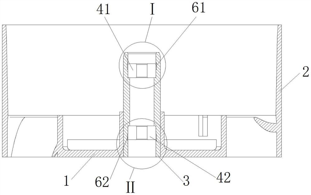
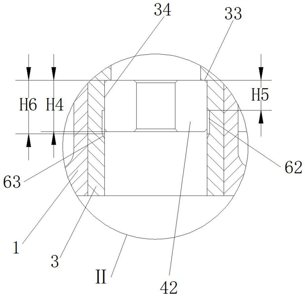
[0036] Please refer to Figure 1 to Figure 5, the present invention provides a middle pipe with an annular groove structure, including a middle pipe 3, the middle pipe 3 is installed inside the stator hub 1, and the stator hub 1 is installed inside the outer frame 2, so One end of the middle tube 3 is fixedly equipped with a first ball bearing 41 through adhesive bonding, and the other end is fixedly equipped with a second ball bearing 42 through adhesive bonding. The first ball bearing 41 and the second ball bearing The bearings 42 are all fixedly installed on the middle pipe 3 by adhesive bonding.

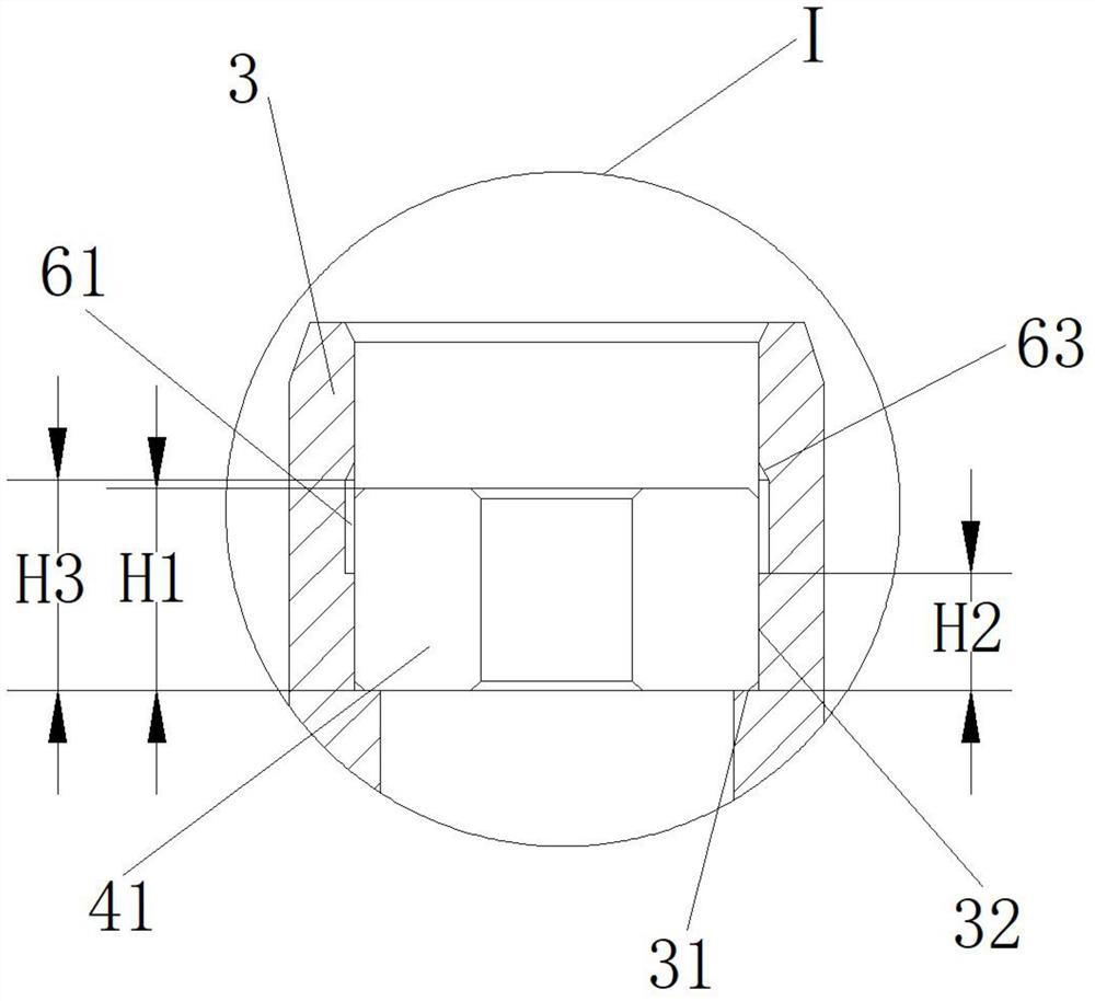
[0037] Such as figure 2 As shown, one end of the middle tube 3 is provided with a first axial support ring end face 31 and a first radial support ring face 32, and the first axial support ring end face 31 is the axial direction of the first ball bearing 41. Support, the first radial support annular surface 32 is radially supported by the first ball bearing 41, the first radial...

Embodiment 2

[0051] Embodiment 2 of the present invention provides a process for assembling the middle tube with an annular groove structure into a ball bearing described in Embodiment 1, including the following steps:

[0052] Step S1: Place the bottom of the outer frame 2 downwards, and install the first ball bearing 41 into one end of the middle tube 3, specifically, the first annular groove 61, the first ball bearing 41 and the middle tube 3 A first open communication chamber for containing the adhesive is formed.

[0053] Step S2: Extend the liquid injection nozzle into the leaking part of the first annular groove 61, inject the adhesive into the inside of the first annular groove 61, and let it stand for a period of time so that the adhesive can fully flow into the first ball bearing 41 and the middle pipe 3, and the adhesive is initially solidified between the first ball bearing 41 and the middle pipe 3, so as to initially fix the first ball bearing 41.

[0054] Step S3: place the ...


PUM


Abstract

The invention discloses a middle pipe with an annular groove structure. The middle pipe comprises a middle pipe body, the middle pipe body is arranged in a stationary blade hub, a first ball bearing is fixedly arranged at one end of the middle pipe body through adhesive in a bonding manner, a second ball bearing is fixedly arranged at the other end of the middle pipe body through the adhesive in a bonding manner, a first radial supporting circular ring surface is arranged at one end of the middle pipe body, a second radial supporting circular ring surface is arranged at the other end of the middle pipe body, the first radial supporting circular ring surface is provided with a first annular groove, the first annular groove is higher than the first ball bearing, the second radial supporting circular ring surface is provided with a second annular groove, and the second annular groove is higher than the second ball bearing. The concentricity of the two assembled ball bearings is improved, the reliability of the fan is improved, and the service life of the fan is prolonged.

Description

technical field [0001] The invention relates to the technical field of fan mid-pipe structure improvement, in particular to a mid-pipe with an annular groove structure and a process for installing a ball bearing. Background technique [0002] At present, the size of the electronic equipment system is shrinking day by day. The cooling fan needs to provide the highest heat dissipation performance in the limited installation space to meet the market demand. Therefore, the industry has more and more demand for high-speed fans. In order to reduce the overall To reduce the vibration and ensure the life of the high-speed fan, the high-speed fan generally adopts the assembly process of ball bearing outer ring and middle tube fixed. [0003] There are generally two fixing methods for fixing the middle tube of the high-speed fan and the outer ring of the ball bearing: one is to fix by adhesive bonding; the other is to fix by interference fit. Using adhesive bonding and fixing technol...

Claims


Application Information

Patent Timeline
Patent Type & Authority Applications(China)
IPC IPC(8): F16C35/067F16C41/00F16B11/00F04D25/08
Inventor 贾自周
Owner 东莞市鸿盈电子科技有限公司
Why Eureka
Try Eureka