Middle pipe with liquid injection groove and groove structure and process for installing ball bearing

A technology of ball bearings and liquid injection tanks, which is applied in the direction of shafts and bearings, rigid supports of bearing components, bearing components, etc., which can solve problems such as complex assembly, difficulty in ensuring concentricity, and inability to meet the fixed requirements of ball bearings

Pending Publication Date: 2021-04-20
东莞市鸿盈电子科技有限公司
View PDF0 Cites 0 Cited by
  • Summary
  • Abstract
  • Description
  • Claims
  • Application Information

AI Technical Summary

Problems solved by technology

Using adhesive bonding and fixing technology, firstly, a layer of adhesive is applied on the inner surface of the middle tube, and then the ball bearing is installed inside the middle tube, and the ball bearing is fixed inside the middle tube by the adhesive, however Using the above assembly method, the adhesive may pass through the dust cover on the ball bearing and enter the interior of the ball bearing, which will reduce the life of the fan or cause the fan to fail
Using the assembly process of interference fit, first of all, the realization of interference fit requires more production equipment, the assembly is more complicated, and the production cost is higher. Then, the concentricity of the upper and lower ball bearings after assembly is greatly affected by the middle tube. , concentricity is difficult to guarantee
[0004] The assembly process of the above two structures can no longer meet the market's fixed demand for ball bearings in high-speed fans

Method used


Image

  • Middle pipe with liquid injection groove and groove structure and process for installing ball bearing
  • Middle pipe with liquid injection groove and groove structure and process for installing ball bearing
  • Middle pipe with liquid injection groove and groove structure and process for installing ball bearing

Examples


Embodiment 1

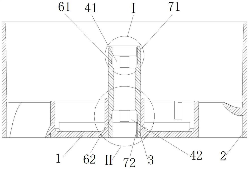
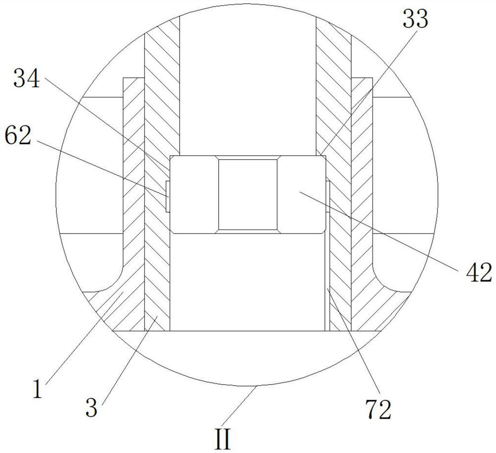
[0038] Please refer to figure 1 , Embodiment 1 of the present invention provides a middle pipe with a liquid injection groove and a groove structure, including a middle pipe 3, the middle pipe 3 is installed inside the stator hub 1, and the stator hub 1 is installed outside Inside the frame 2, one end of the middle tube 3 is bonded and fixed with a first ball bearing 41, and the other end is bonded and fixed with a second ball bearing 42. The first ball bearing 41 and the second ball bearing 42 are all fixedly installed on the middle pipe 3 by adhesive bonding.

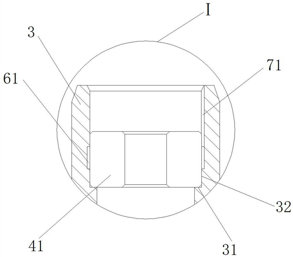
[0039] One end of the middle tube 3 is provided with a first axial support ring end face 31 and a first radial support ring face 32, and the first axial support ring end face 31 is axially supported by the first ball bearing 41, so The first radial support annular surface 32 is radially supported by the first ball bearing 41, the first radial support annular surface 32 is provided with a first groove, and the first r...

Embodiment 2

[0048] Please refer to Figure 4 , Embodiment 2 of the present invention provides a middle pipe with a liquid injection groove and a groove structure. The difference from Embodiment 1 is that only the first annular groove 61 and the second annular groove 62 are changed to the first The helical groove 81 and the second helical groove 82 only change the shape of the groove containing the adhesive, so that the force uniformity of the first ball bearing 41 and the second ball bearing 42 is further improved.

[0049] Such as Figure 4 and 5 As shown, the first groove is a first helical groove 81, the first helical groove 81 spirally surrounds the first ball bearing 41, and the axial height of the first helical groove 81 is less than or equal to The height of the first ball bearing 41, the first radial support annular surface 32 is also provided with a first liquid injection groove 71, the first liquid injection groove 71 is a vertical groove, and the first liquid injection groove...

Embodiment 3

[0056] The third embodiment of the present invention provides that the present invention also provides a process for assembling the middle tube with a liquid injection tank and a groove structure described in the first and second embodiments to install the ball bearing, including the following steps :

[0057] Step S1: Place the bottom of the outer frame 2 downwards, and put the first ball bearing 41 into one end of the middle tube 3. Specifically, the first annular groove 61, the first ball bearing 41, and the first liquid injection tank Between 71 and the middle pipe 3, a first open communication chamber for accommodating the adhesive is formed;

[0058] Alternatively, a first open communicating spiral chamber for accommodating adhesive is formed among the first spiral groove 81 , the first ball bearing 41 , the first liquid injection groove 71 and the middle tube 3 .

[0059]Step S2: Extend the liquid injection nozzle into the first liquid injection groove 71, inject or fl...


PUM


Abstract

The invention discloses a middle pipe with a liquid injection groove and a groove structure. The middle pipe comprises a middle pipe body, the middle pipe body is arranged in a stationary blade hub, a first ball bearing is fixedly arranged at one end of the middle pipe body through an adhesive in a bonding manner, a second ball bearing is fixedly arranged at the other end of the middle pipe body through an adhesive in a bonding manner, a first radial support ring surface is arranged at one end of the middle pipe body, and a second radial supporting ring surface is arranged at the other end of the middle pipe body; and the first radial supporting ring surface is provided with a first groove, the first radial supporting ring surface is further provided with a first liquid injection groove, the first liquid injection groove is connected with the first groove, the second radial supporting ring surface is provided with a second groove, the second radial supporting ring surface is further provided with a second liquid injection groove, and the second liquid injection groove is connected with the second groove. According to the middle pipe, the stress of a ball bearing is improved, the service life of the bearing is prolonged, the concentricity of the ball bearing and the middle pipe is ensured, and the process difficulty of adhesive injection is reduced.

Description

technical field [0001] The invention relates to the technical field of fan mid-pipe structure improvement, in particular to a mid-pipe with a liquid injection groove and a groove structure and a process for installing a ball bearing. Background technique [0002] At present, the size of the electronic equipment system is shrinking day by day. The cooling fan needs to provide the highest heat dissipation performance in the limited installation space to meet the market demand. Therefore, the industry has more and more demand for high-speed fans. In order to reduce the overall To reduce the vibration and ensure the life of the high-speed fan, the high-speed fan generally adopts the assembly process of ball bearing outer ring and middle tube fixed. [0003] There are generally two fixing methods for fixing the middle tube of the high-speed fan and the outer ring of the ball bearing: one is to fix by adhesive bonding; the other is to fix by interference fit. Using adhesive bondi...

Claims


Application Information

Patent Timeline
Patent Type & Authority Applications(China)
IPC IPC(8): F16C35/063F16C41/00F16C3/02
Inventor 贾自周
Owner 东莞市鸿盈电子科技有限公司
Why Eureka
Try Eureka