Magnetic-coupling step-by-step excitation water flow generator

A water flow generator, magnetic coupling technology, applied in the direction of generator/motor, piezoelectric effect/electrostrictive or magnetostrictive motor, electrical components, etc., can solve the problem of power supply of monitoring system, which has not been well solved, It has not been popularized and applied in a large area, and has achieved the effects of simple structure, high reliability and strong fluid adaptability

Active Publication Date: 2017-12-15
ZHEJIANG NORMAL UNIVERSITY
View PDF16 Cites 0 Cited by
  • Summary
  • Abstract
  • Description
  • Claims
  • Application Information

AI Technical Summary

Problems solved by technology

Although some of the monitoring methods currently proposed are relatively mature at the technical level, they have not been popularized and applied on a large scale. One of the main reasons is that the power supply problem of the monitoring system has not been well resolved.

Method used


Image

  • Magnetic-coupling step-by-step excitation water flow generator
  • Magnetic-coupling step-by-step excitation water flow generator
  • Magnetic-coupling step-by-step excitation water flow generator

Examples


Embodiment Construction

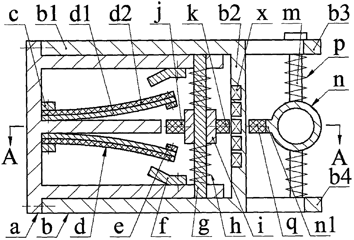
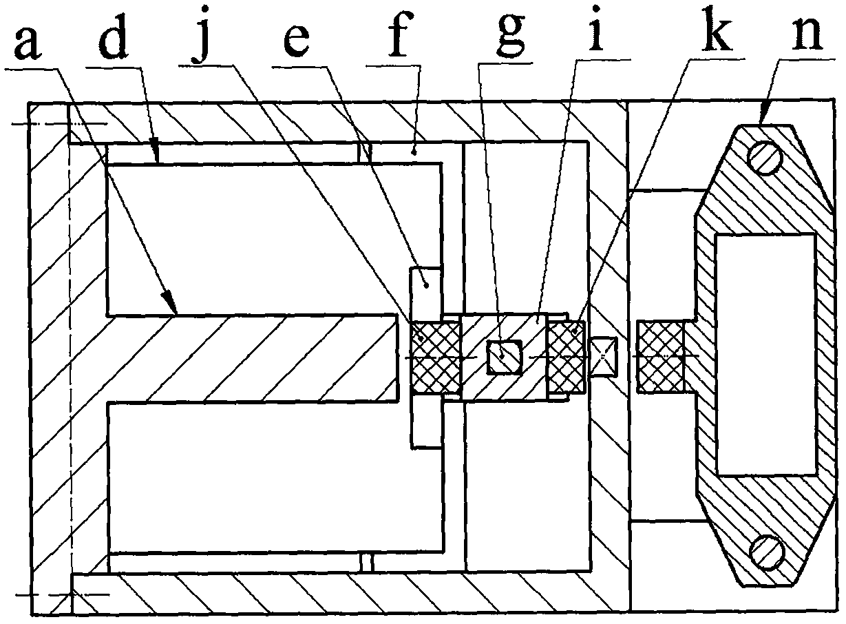
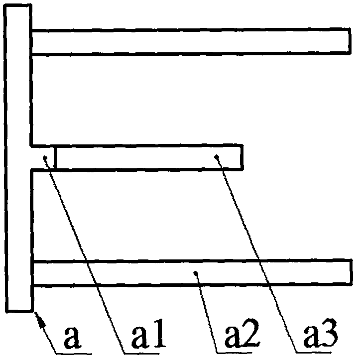
[0012] The end cover a is installed on the end of the cylinder wall b1 of the shell b by screws. There is a boss a1 and two inner ear plates a2 on the end cover a. The boss a1 is located at the center of the end cover a, and the two inner ear plates a2 Symmetrically arranged on the upper and lower sides of the boss a1, the boss a1 is provided with a limit plate a3; the upper and lower sides of the boss a1 are installed with a transducer d through screws and a pressure plate c, and the transducer d is composed of the substrate d1 and piezoelectric The film d2 is bonded, the base plate d1 is installed close to the boss a1, the free end of the transducer d is installed with the suspended magnet e through the screw; the inner ear plate a2 is installed with the reed f through the screw, and the reed f is located in the transducer d Above or below the free end; a square guide column g is installed on the two inner ear plates a2, two inner springs h and an inertia block i are sleeved ...


PUM


Abstract

The present invention relates to a magnetic-coupling step-by-step excitation water flow generator and belongs to the power generation field. An end cover is installed at an end portion of the cylinder wall of a shell; the end cover is provided with a boss and two inner ear plates, wherein the boss is provided with a limiting plate; the upper side and lower side of the boss are provided with transducers; the free ends of the transducers are provided with suspended magnets; a square guide column installed on the inner ear plates is sleeved with two inner springs and an inertia block, wherein the inner springs are located at the upper side and lower side of the inertia block respectively; the left side and right side of the inertia block are provided with a suspension magnet and an excited magnet respectively; the suspension magnet is located between the two suspended magnets; the suspension magnet and the suspended magnets repel each other so as to make the transducers bent and deformed; a coil is embedded at the inner side of the bottom wall of the shell; the external side of the bottom wall of the shell is provided with an upper ear plate and a lower ear plate; the upper ear plate and the lower ear plate are connected with one another through two round guide columns; two ends of a bluff body sleeve the two round guide columns; the guide columns are sleeved with two outer springs; two ends of each of the two outer springs are pressed on the bluff body and the upper ear plate or the lower ear plate; and the wing plate of the bluff body is provided with an excitation magnet; and the excitation magnet is installed in a manner that the magnetic poles of the excitation magnet are opposite to the magnetic poles of the excited magnet, wherein the magnetic poles have different polarities.

Description

technical field [0001] The invention belongs to the technical field of power generation, and in particular relates to a water flow generator excited by magnetic coupling step by step, which supplies power to a river monitoring system. Background technique [0002] There are thousands of rivers in our country. In recent years, due to insufficient treatment of industrial waste and sewage, soil erosion and improper use of pesticides and fertilizers, most of the rivers have been polluted to a certain extent. In addition, due to the imperfect flood control facilities of small and medium-sized rivers in many areas, or even no flood control facilities, when the flood season comes, it may lead to dangers such as breaking or overflowing of the embankment, which directly threatens the life and property safety of the people along the coast. Therefore, river monitoring has been highly valued by relevant state departments. The Ministry of Water Resources once planned to achieve full cov...

Claims


Application Information

Patent Timeline
Patent Type & Authority Applications(China)
IPC IPC(8): H02K35/02H02N2/18
CPCH02K35/02H02N2/185
Inventor 王淑云朱雅娜阚君武
Owner ZHEJIANG NORMAL UNIVERSITY
Why Eureka
Try Eureka