Flowmeter

A flowmeter and fluid cavity technology, applied in the field of flowmeter, can solve the problems affecting the accuracy and real-time performance of data statistics, the problem of power supply can not be solved well, and the inconvenience of automatic meter reading system pre-laying and other problems

Active Publication Date: 2021-09-10
益都智能技术(北京)股份有限公司
View PDF5 Cites 1 Cited by
  • Summary
  • Abstract
  • Description
  • Claims
  • Application Information

AI Technical Summary

Problems solved by technology

Manual meter reading is not only inefficient and wastes manpower and material resources, but more importantly, meter readers often go back and forth many times in vain due to no one in the household, which seriously affects the accuracy and real-time performance of data statistics. Therefore, people began to develop tap water and gas Remote automatic meter reading system, and it can be applied in new houses
Although the data processing and transmission technology of the existing meter reading system is very mature, it is still difficult to popularize and apply it in old residential areas. Laying cables, so people are trying to develop a flow meter that can be self-sufficient in electrical energy
[0003] At present, people have developed various forms of gas and tap water meters powered by piezoelectric power generation, such as Chinese patent ZL2015100072748, etc. The existing meters use the intermittent coupling force between the excitation magnet and the excited magnet to achieve power transmission. , starting resistance is large, not suitable for low-speed water flow and gas flow measurement

Method used


Image

  • Flowmeter
  • Flowmeter
  • Flowmeter

Examples


Embodiment Construction

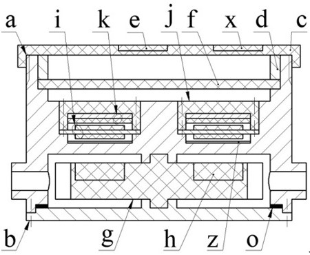
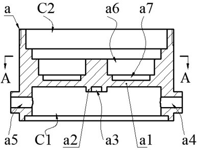
[0028] The partition a1 divides the housing a into a coaxial fluid chamber C1 and an electric control chamber C2. The electric control chamber C2 is a stepped chamber. The side of the partition a1 facing the fluid chamber C1 is called the bottom wall of the fluid chamber, facing the electric control chamber. One side of C2 is called the bottom wall of the electronic control chamber; the bottom wall of the fluid chamber is provided with an upper baffle a2 and an upper shaft hole a3, the upper shaft hole a3 is coaxial with the fluid chamber C1, and the upper shaft hole a3 is located on the upper baffle On a2; the side wall of the fluid chamber C1 is provided with a coaxial inlet a4 and outlet a5; the bottom wall of the electric control chamber is provided with an annular groove a6 and a sunken cavity a7, the width of the annular groove a6 is greater than the diameter of the sunken cavity a7, and the sunken cavity a7 The center of the cavity a7 is located on the center line of sym...


PUM


Abstract

The invention relates to a flowmeter, and belongs to the technical field of new energy and flow instruments. A shell comprises a fluid cavity and an electric control cavity, a shaft hole is formed in the bottom wall of the fluid cavity, an inlet-outlet is formed in the side wall, and an annular groove and a sinking cavity are formed in the bottom wall of the electric control cavity. A sealing cover is arranged at the end part of the fluid cavity; the circuit board is pressed in the electric control cavity by a cover plate; a magnet is arranged on the wheel disc with the half shaft and the blades, and the half shaft is arranged in the shaft hole; the elastic film is pressed on the bottom wall of the annular groove through the annular plate provided with the sinking groove; a limiting pad or a fixed composite film consisting of a fixed electrode and a fixed friction layer is arranged on the bottom walls of the sinking groove and the sinking cavity; the elastic film is an independent metal layer or a composite film formed by the metal layer, a piezoelectric layer and a dynamic friction layer; the metal layer and the dynamic friction layer form a dynamic composite film; the metal layer and the piezoelectric layer form a piezoelectric energy harvesting unit, the movable and fixed composite films form a friction energy harvesting unit, and mechanical energy is converted into electric energy through bending deformation of the composite films and contact and separation between the composite films and the fixed composite films; and the number of the pulse voltage signals in unit time is used for representing the fluid flow.

Description

technical field [0001] The invention belongs to the technical field of new energy and flow meters, and in particular relates to a flow meter, which is used to measure the flow of residential gas and tap water. Background technique [0002] Tap water is an indispensable consumer product in the daily life of urban residents, and its consumption records and statistics are still mainly done manually. Manual meter reading is not only inefficient and wastes manpower and material resources, but more importantly, meter readers often go back and forth many times in vain due to no one in the household, which seriously affects the accuracy and real-time performance of data statistics. Therefore, people began to develop tap water and gas Remote automatic meter reading system, and can be applied in new houses. Although the data processing and transmission technology of the existing meter reading system is very mature, it is still difficult to popularize and apply it in old residential a...

Claims


Application Information

Patent Timeline
Patent Type & Authority Applications(China)
IPC IPC(8): H02N2/18H02N1/04H02J7/35H02J7/34G01F1/28
CPCH02N2/185H02N1/04H02J7/35H02J7/345G01F1/28H02J2207/50
Inventor 张忠华李哲祝孟松杜洁雅陈松王淑云程光明吴鸣曾平
Owner 益都智能技术(北京)股份有限公司
Why Eureka
Try Eureka