Telescopic pipeline flow generator

A pipeline flow and generator technology, applied in the direction of generator/motor, piezoelectric effect/electrostrictive or magnetostrictive motor, electrical components, etc., can solve natural environmental pollution, limited battery life, economic loss, etc. problems, to achieve the effects of strong environmental adaptability, effective frequency bandwidth, and strong power generation capacity

Active Publication Date: 2020-02-04
ZHEJIANG NORMAL UNIVERSITY
View PDF13 Cites 1 Cited by
  • Summary
  • Abstract
  • Description
  • Claims
  • Application Information

AI Technical Summary

Problems solved by technology

[0002] During the operation of oil and gas pipelines, due to natural corrosion, natural force majeure, especially man-made theft, oil and gas pipeline leakage incidents occur from time to time, which not only caused huge economic losses, but also caused serious pollution to the surrounding natural environment.
In the past, it was maintained by manual inspection methods, but because the pipeline laying distance is long, and it is often in an inaccessible or inconvenient place, it is difficult to detect leakage in time and repair i

Method used


Image

  • Telescopic pipeline flow generator
  • Telescopic pipeline flow generator
  • Telescopic pipeline flow generator

Examples


Embodiment Construction

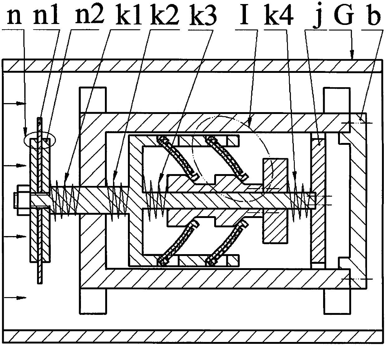
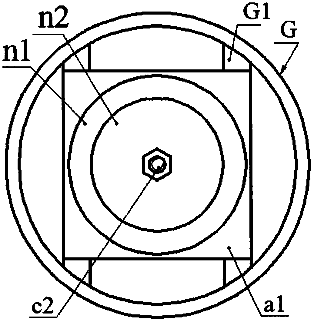
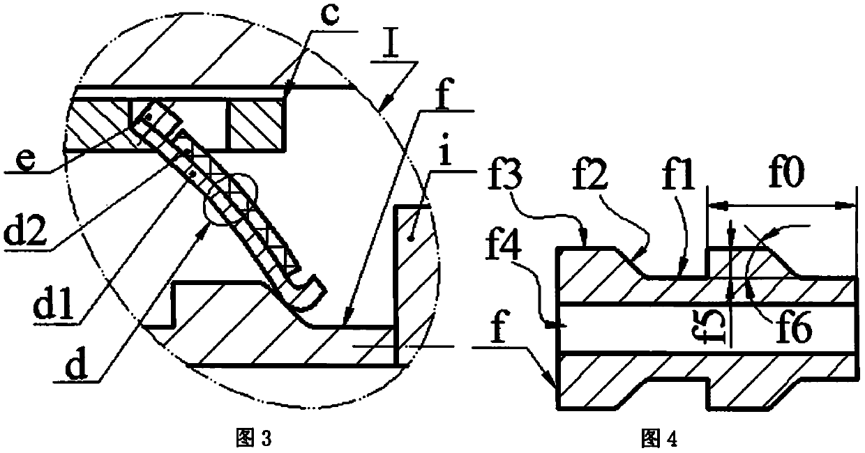
[0014] On the inner wall of the pipe G, a shell a is installed through the radial plate G1, and the end of the side wall a2 of the shell a is installed with an end cover b through screws; the left and right pins of the vertical plate c1 of the bracket c are respectively provided with a left pin c2 and a right pin c3, the left pin c2 and the right pin c3 are coaxial, and the cross sections of the left pin c2 and the right pin c3 are circular and square, respectively; There is an inclined installation surface c5, the installation surface c5 is located on the hole wall on the horizontal plate c4, the acute angle c6 formed by the installation surface c5 and the horizontal plate c4 is the installation angle, and the installation angle is greater than 30 degrees; the bracket c is placed in the body cavity of the shell a Inside a3 and the left pin c2 protrudes through the guide hole on the bottom wall a1 of the shell. The end of the left pin c2 is installed with a blunt body n through...


PUM


Abstract

The invention relates to a telescopic pipeline flow generator, and belongs to the technical field of new energy and pipeline monitoring. A shell is installed on the inner wall of a pipeline through aspoke plate; an end cover is installed on the end part of the side wall of the shell; a left pin and a right pin are arranged at the left and right sides of the vertical plate of a bracket; transverseplates with inclined installation surfaces are arranged at the right sides of the upper and lower ends of the vertical plate; the bracket is arranged in the shell; therefore, the left pin extends outthrough the bottom wall of the shell; a bluff body is arranged on the end part of the left pin; a support spring and a buffer spring respectively sleeve the left pin among the bottom wall of the shell, the bluff body and the vertical plate of the bracket; a left spring, an exciter, a frequency modulation block and a right spring sequentially sleeve the right pin from left to right; the exciter isconnected with the frequency modulation block; the right end of the right spring abuts on a stop block on the end part of the right pin; both the upper and lower sides of the exciter are each provided with a movable cam composed of a bottom surface, an inclined surface and a top surface along the axial direction of the pin hole; one end of a piezoelectric vibrator is installed on the installationsurface of the bracket; when non-working, the flange of the substrate of the piezoelectric vibrator is contacted with the midpoint of the inclined surface of the cam; furthermore, the assembly pre-bending deflection is one half of the allowable value thereof; and the allowable deflection of the piezoelectric vibrator is greater than the lifting stroke of the cam.

Description

technical field [0001] The invention belongs to the technical field of new energy and oil and gas pipeline monitoring systems, and in particular relates to a telescopic pipeline flow generator. Background technique [0002] During the operation of oil and gas pipelines, oil and gas pipeline leakage incidents occur frequently due to natural corrosion, force majeure of nature, especially man-made theft, which not only caused huge economic losses, but also caused serious pollution to the surrounding natural environment. In the past, it was maintained by manual inspection methods, but because the pipeline laying distance is long, and it is often in an inaccessible or inconvenient place, it is difficult to detect leakage in time and repair it in time, so people have proposed various types of pipeline leakage monitoring or anti-theft systems. , some technologies are relatively mature; but the power supply problem of the oil and gas pipeline monitoring system has not been well reso...

Claims


Application Information

Patent Timeline
IPC IPC(8): H02N2/18
CPCH02N2/185H02N2/186
Inventor 张忠华林仕杰李建平柴君凌万嫩郑佳佳黄芳胜程光明
Owner ZHEJIANG NORMAL UNIVERSITY
Why Eureka
Try Eureka