Silkworm breeding frame

A technology of breeding racks and silkworms, applied in the field of silkworm breeding racks, can solve the problems of easy accidental injury to silkworms, death, time-consuming and labor-intensive, etc.

Active Publication Date: 2017-12-19
NANJING ZHIQIAO AGRI CO LTD
3 Cites 1 Cited by

AI-Extracted Technical Summary

Problems solved by technology

The breeding tools in the existing silkworm breeding technology include wooden frames and multi-layer silkworm plaques placed on the wooden frames. During the whole breeding process of silkworms, it is necessary to go through the process of removing silkworm excrement and replacing fresh mulberry leaves for many times, especially for silkworms. The process of removing silkworm excrement and replacing mulberry leaves by large silkworms is relatively frequent. Usually, it ...

Method used

In above-mentioned technical scheme, the silkworm plaque 10 on the silkworm plaque 10 frame of the present invention can realize the adjustment of position on the vertical direction by the up and down movement of a pair of second crosspiece 6, and a silkworm plaque 10 frame can be placed relatively More silkworm plaques 10, breed more silkworms, improve space utilization, operators can complete the operation on the ground, save trouble and effort, and have high practical value; utilize the upward property of silkworms to place fresh mulberry leaves on the The upper part of the mulberry silkworm, so that the mulberry silkworm can move to the fresh mulberry leaves by itself, and then the first pin shaft 711 and the second pin shaft 721 are simultaneously rotated to drive the flipping of the upper inverted silkworm plaque 10, so that the silkworm plaque 10 can be turned over without directly contacting the silkworm. Complete...

Abstract

The invention discloses a silkworm breeding frame which comprises a main bracket, a secondary bracket, two pairs of first cross beams, multiple pairs of second cross baffles, first stretchable rods, second stretchable rods, a plurality of silkworm flats, a plurality of first slide blocks and two pairs of second slide blocks, wherein the main bracket comprises two pairs of first vertical columns and four first cross beams; the secondary bracket comprises a pair of second vertical columns and second cross beams; the two pairs of first cross beams are located between the main bracket and the secondary bracket; the second cross baffles are arranged between the two pairs of first vertical columns from top to bottom; the first stretchable rods and the second stretchable rods are all vertically arranged and fixed on the adjacent parallel first cross beams and second cross beams; one silkworm flat is corresponding to a pair of cross baffles; a pair of first slide blocks are arranged on one second cross baffle in a sliding form; the two pairs of second slide blocks are respectively arranged on a pair of second cross baffles on the upper part. The silkworm breeding frame is capable of quickly avoiding the processes of removing excrement and replacing folium mori in a time-saving and labor-saving way without direct contact with the silkworm, is capable of increasing the silkworm breeding effect and has higher practical value.

Application Domain

Animal husbandry

Technology Topic

EngineeringBombyx mori

Image

  • Silkworm breeding frame
  • Silkworm breeding frame
  • Silkworm breeding frame

Examples

  • Experimental program(1)

Example Embodiment

[0031] The present invention will be further described in detail below with reference to the accompanying drawings and embodiments, so that those skilled in the art can implement it with reference to the text of the description.
[0032] It should be understood that terms such as "having", "including" and "including" used herein do not equate the presence or addition of one or more other elements or combinations thereof.
[0033] It should be noted that the experimental methods described in the following embodiments are conventional methods unless otherwise specified, and the reagents and materials, unless otherwise specified, can be obtained from commercial sources.
[0034] In the description of the present invention, the terms "horizontal", "vertical", "upper", "lower", "front", "rear", "left", "right", "vertical", "horizontal", " The orientation or positional relationship indicated by "top", "bottom", "inner", "outer", etc. are based on the orientation or positional relationship shown in the drawings, and are only for the convenience of describing the present invention and simplifying the description, and are not indicative or implied. The device or element referred to must have a specific orientation, be constructed and operated in a specific orientation, and therefore cannot be understood as a limitation of the present invention.
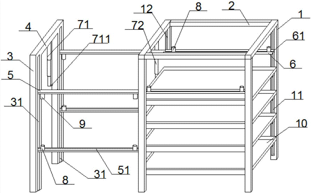
[0035] Such as Figure 1~4 As shown, the present invention provides a silkworm breeding frame, which includes:
[0036] The main support is a rectangular parallelepiped frame structure. The main support includes two pairs of first uprights 1 and four horizontally arranged first beams 2 that connect the upper ends of the four first uprights 1 in sequence. The cross section of a column 1 is rectangular, and a pair of the first column 1 located on the right side of the main support is provided with a first sliding groove 11 extending in the vertical direction on two opposite sides of the first column 1 respectively. , Two second sliding grooves 12 that are parallel to each other and extend in a vertical direction are respectively provided on two opposite side surfaces of the pair of first uprights 1 located on the left side of the main support;
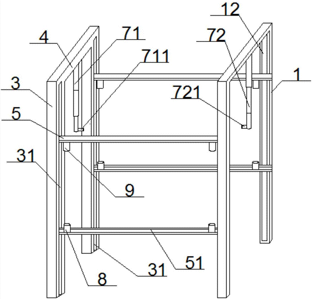
[0037] The auxiliary bracket is a vertically arranged door frame structure located on the left side of the main bracket and parallel to the left side of the main bracket. The auxiliary bracket includes a pair of second uprights 3 and two second The upper ends of the two uprights 3 are connected with a horizontally arranged second crossbeam 4, the cross section of the second upright 3 is rectangular, and a pair of second uprights 3 are respectively provided on two opposite sides The third chute 31 extending in the direction;
[0038] Two pairs of first crosspieces 5, which are located between the main support and the auxiliary support, any one of the first crosspieces 5 is arranged horizontally and perpendicular to the left side of the main support, and any pair of The plane formed by the first crosspiece 5 is a horizontal plane, one end of the first crosspiece 5 close to the second upright 3 is slidably connected to the third chute 31, and the other end is connected to one close to the auxiliary bracket. The second chute 12 is slidably connected, so that the first crosspiece 5 can move up and down relative to the first upright column 1 and the second upright column 3; the longitudinal section of the first crosspiece 5 is rectangular and is located A T-shaped first opening 51 extending along the length of the first rung 5 penetrates through the upper side of the first rung 5 at the lower part, and is located on the lower side of the first rung 5 at the upper part There is a T-shaped second opening 62 extending along the length of the first crosspiece 5 therethrough;
[0039] A plurality of pairs of second rungs 6 are arranged from top to bottom between two pairs of said first uprights 1, any one of said second rungs 6 is parallel to said first rung 5, any one pair The plane formed by the second rung 6 is a horizontal plane. One end of any second rung 6 close to the right side of the main support is slidably connected to the first chute 11, and the other end is close to the One of the second sliding grooves 12 on the right side of the main bracket is slidably connected, so that the second crosspiece 6 can move up and down relative to the first column 1, and the longitudinal section of the second crosspiece 6 is rectangular, There is a T-shaped third opening extending along the length of the second rung 6 through the upper side of the second rung 6. When a pair of the second rungs 6 move to the lower side When a pair of the first crosspieces 5 are flush, the end of one of the first openings 51 is connected to the end of the third opening, and the horizontal center lines of the two are on the same straight line, forming a horizontal line. Straight slide;
[0040] The first telescopic rod 71 and the second telescopic rod 72 are both vertically arranged and located on the same vertical surface. The first telescopic rod 71 and the second telescopic rod 72 are respectively fixed to a parallel and adjacent first cross beam 2 On the upper and a second crossbeam 4, the first telescopic rod 71 includes a plurality of first rod bodies whose diameters gradually increase from the inside to the outside and are sequentially sleeved. The upper end of the first rod body located in the outermost layer is fixed to, The middle part of the lower side of the first crossbeam 2 that is parallel and close to the second crossbeam 4 is provided with a horizontal first pin at the position near the lower end of the outer surface of the first rod body located in the innermost layer 711, one end of the first pin shaft 711 is bearing-connected with the outer surface of the first rod, and the other end extends in a direction close to the auxiliary bracket; the second telescopic rod 72 includes a plurality of sleeves sequentially extending from the inside to the outside The upper end of a second rod located in the outermost layer is fixed to the middle part of the lower side of the second beam 4 that is close to and parallel to the first beam 2, and a second rod located in the innermost layer A horizontally arranged second pin 721 is provided near the lower end of the outer surface. One end of the second pin 721 is bearing-connected with the outer surface of the second rod body, and the other end faces toward the direction of the main support extend;
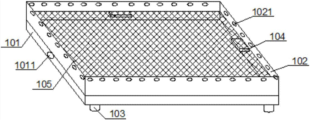
[0041] A plurality of silkworm plaques 10, a pair of the second crosspieces 6 is provided with one silkworm plaque 10, the silkworm plaque 10 is slidably connected to a pair of the second crosspieces 6, and the silkworm plaque 10 includes an upper opening A box with a rectangular parallelepiped structure, a screen 105 horizontally connected to the box, and a plurality of tension springs located between the bottom of the box and the screen 105; four side plates of the box 102 is provided with a hook hole 1021 near the upper edge, a blind hole 1011 is respectively provided on two opposite sides of the bottom plate 101, the two blind holes 1011 are coaxial, and the four A limit block 104 is respectively provided on the inner wall, and the four limit blocks 104 are located on the same horizontal plane; the screen 105 is located on the four limit blocks 104; the lower end of any one of the tension springs is fixed to On the inner wall of the box body, the upper hook is set in the grid of the screen 105;
[0042] The tension spring is arranged such that when the tension spring is in a natural expansion and contraction state, the screen 105 rests on the four limit blocks 104, and the screen 105 is connected to the upper edge of the box body. The ratio of the distance to the height of the box body side plate 102 is 2:5; when the tension spring is stretched to the extreme position, the plane of the screen 105 is flush with the plane of the edge of the box body's opening end;
[0043] There are a plurality of pairs of first sliders 8, one of the second crosspiece 6 corresponds to a pair of the first sliders 8, and any one of the first sliders 8 is a vertically arranged hollow cylinder with open ends, The circumferential surface of the first sliding block 8 close to the upper end is provided with a first through hole penetrating in the radial direction; the lower end edge of any one of the first sliding blocks 8 extends horizontally in a direction away from its axis An annular first snap ring, the first snap ring can be horizontally slidably clamped on the bottom of the third opening;
[0044] Two pairs of second sliding blocks 9 are respectively arranged on a pair of said first rungs 5 ​​located at the upper part, and one pair of said second sliding blocks 9 corresponds to one of said first rungs 5 ​​located at the upper part, either The first sliding block 8 is a vertically arranged hollow cylinder with two ends open, and the second sliding block 9 is provided with a second through hole penetrating in a radial direction on the circumferential surface close to the lower end; An annular second snap ring extends horizontally from an upper edge of the second sliding block 9 in a direction away from its axis, and the second snap ring is horizontally slidably clamped on the bottom of the second opening 62.
[0045] In the above technical solution, the silkworm plaque 10 on the silkworm plaque 10 frame of the present invention can be adjusted in the vertical direction through the up and down movement of a pair of second crosspieces 6, and one silkworm plaque 10 frame can hold more silkworms. Plaque 10, breeding more silkworms, improving space utilization, operators can complete operations on the ground, saving time and effort, and has high practical value; using the upward nature of silkworms to place fresh mulberry leaves on top of the silkworms , So that the silkworm can move to the fresh mulberry leaf by itself, and then the first pin 711 and the second pin 721 rotate at the same time to drive the upside-down silkworm plaque 10 to flip, so as to realize the completion without direct contact with the silkworm. The displacement of the silkworm achieves the purpose of removing sand and refueling.
[0046] In another technical solution, in the silkworm breeding frame, the silkworm plaque 10 is sleeved by four third sliders 103 and two pairs of four second sliders 9 on a pair of second crosspieces 6 It is also fixed with a pin to realize the sliding connection with the second crosspiece 6 to facilitate the removal and fixation of the silkworm plaque 10, the structure design is simple, the cost is low, and the utility model is relatively high.
[0047] In another technical solution, in the silkworm breeding frame, a third rod is horizontally arranged between a pair of the second crosspieces 6, and both ends of the third rod are connected to the two second The right end of the crosspiece 6 is fixedly connected. The vertical position of the pair of second rails 6 can be adjusted by directly applying upward/downward thrust to the third rod body.
[0048] In another technical solution, in the silkworm breeding frame, a fourth rod is horizontally arranged between a pair of the first crosspieces 5, and two ends of the fourth rod are connected to the two first The left end of the crosspiece 5 is fixedly connected. The vertical position of the pair of first rails 5 can be adjusted by directly applying upward/downward thrust to the fourth rod body.
[0049] In another technical solution, in the silkworm breeding frame, the mesh size of the screen 105 is 4 mm. Make sure that the silkworm excrement can fall into the bottom of the box and the silkworm and mulberry leaf residues will not fall off, so as to collect clean silkworm excrement, so that the products can be better separated and collected.
[0050] In another technical solution, in the silkworm breeding frame, the four side plates 102 of the silkworm plaque 10 are each provided with a plurality of circular ventilation holes. Ensure good ventilation inside the silkworm plaque 10.
[0051] The working principle of the present invention: First, hook the upper ends of the four drawstring springs in the grids opposite to the screen 105, and place the screen 105 horizontally on the four limit blocks 104 of the box. Fresh mulberry leaves are placed on the upper surface of the screen 105 of the plaque 10. The method of placing the mulberry leaves is specifically as follows: multiple mulberry leaves are stacked and multiple mulberry leaves are threaded through a drawstring, and then the multiple mulberry leaves are evenly clothed. To make mulberry leaf strips, prepare multiple mulberry leaf strips in the same way, arrange the multiple mulberry leaf strips in parallel along the width direction of the screen 105, and tie both ends of the drawstring of each mulberry leaf strip to the screen. On the two opposite sides of the net 105, the mulberry leaves almost cover the mesh of the screen 105; then the silkworm is placed on the upper surface of the mulberry leaf, and the four third sliders 103 on the lower surface of the silkworm plaque 10 are respectively The four first sliding blocks 8 are sleeved on a pair of second crosspieces 6, and the four third sliding blocks 103 and the four first sliding blocks 8 are fixed in turn with pins, so that the silkworm plaque 10 is placed horizontally A pair of second rungs 6 are slidably connected to it; a silkworm plaque 10 is placed on each pair of second rungs 6 in the same way;
[0052] When the silkworm plaque 10 needs to remove the silkworm excrement and replace the mulberry leaves, retract the first telescopic rod 71 and the second telescopic rod 72 to the shortest. At this time, the first telescopic rod 71 and the second telescopic rod 72 are located at the first crosspiece 5. And above the second rung 6, move the pair of first rungs 5 ​​located at the bottom up and down relative to the second column 3 to a position flush with the pair of first rungs 5 ​​to be changed, at this time the second rung 6 is connected to the end of the corresponding first rung 5, the second opening 62 and the end of the first opening 51 are connected to form a horizontal linear slide, and the four first sliding blocks 8 are respectively Slide horizontally on a corresponding slide to move the silkworm plaque 10 from a pair of second rungs 6 to a pair of first rungs 5 ​​at the bottom; place between a pair of first rungs 5 ​​at the top Enter an inverted silkworm plaque 10 with fresh mulberry leaves on the screen 105. The silkworm plaque 10 is slidingly connected with a pair of first crosspieces 5 located on the upper part: the four third sliders 103 of the silkworm plaque 10 are respectively Sleeve into the four second sliders 9, and fix the third slider 103 and the second slider 9 with pins, and then move the pair of first crosspieces 5 on the upper part relative to the second upright 3 to drive The silkworm plaque 10 covered with fresh mulberry leaves moves toward the direction of the silkworm plaque 10 to be refilled, and the upper end of the drawstring spring in the silkworm plaque 10 to be refilled is taken out of the mesh of the screen 105, and the screen is released. The net 105 is connected to the box body, and then a plurality of S-shaped hooks are used to connect the screen 105 in the silkworm plaque 10 to be refilled and the hook hole 1021 on the side plate 102 of the silkworm plaque 10 with fresh mulberry leaves. The upper hook of any S-shaped hook body is set in the mesh of the screen 105, and the lower end hook is set in the hook hole 1021. The appropriate height of S can be selected according to the distance between the upper and lower screens 105. The hook-shaped body ensures that the silkworms can touch the fresh mulberry leaves, so that the silkworms can automatically move to the fresh mulberry leaves. Move the pair of first crosspieces 5 on the upper part to the lower screen relative to the second column 3 105 is located above the lower box body. At this time, the rope bodies at both ends of the mulberry leaf strips in the lower screen 105 can be shaken to shake off the silkworm excrement in the screen 105 into the box body and collect the silkworm excrement in the box body. , To realize the separation of silkworm excrement and mulberry leaf residues and easy collection of clean silkworm excrement, which is convenient for the classification and processing of products; after the silkworm is moved to the fresh mulberry leaves, a pair of first horizontal bars 5 The screen 105 that moves down to the lower part of the second column 3 rests on the four limit blocks 104 of the lower box, then remove the multiple S-shaped hooks and move the pair of upper crosspieces upwards, so that The distance between the two screens 105 is increased to facilitate cleaning of the mulberry leaf residues on the upper surface of the lower screen 105. Remove the mulberry leaf strips from the lower screen 105. If there are a few silkworms, they are still on the lower screen. When the mulberry leaves of 105 are on, the silkworm can be driven to the upper surface of the lower screen 105 with a soft brush, and the lower screen 105 from which the mulberry leaf strips are removed is connected to the upper silkworm plaque 10 again through the S-shaped hook body. At the same time, remove the silkworm plaque 10 at the lower part, and extend both the first telescopic rod 71 and the second telescopic rod 72 downward, so that the first pin 711 and the second pin 721 can be inserted into the blind holes 1011 on both sides of the upper silkworm plaque 10 to fix the upper silkworm plaque 10 with the first telescopic rod 71 and the second telescopic rod 72. The pin in the second slider 9 is removed, the third slider 103 and the second slider 9 are removed from the fixed connection, and the upper silkworm plaque 10 is disconnected from the upper first rail 5; it rotates around the horizontal axis of the blind hole 1011 The first pin shaft 711 and the second pin shaft 721 drive the upper silkworm plaque 10 to rotate 180 degrees, so that the upper silkworm plaque 10 rotates from the inverted state to the normal state with the opening upward, completing the reversal of the silkworm plaque 10 so that the silkworm is in a fresh position. Then the silkworm plaque 10 is sleeved and fixed with the first slider 8 on the lower first rail 5 through the third slider 103, and is slidably connected to the lower first rail 5, And move back to the second rail 6, the same method is used to complete all the silkworm plaque 10 sand removal and refueling procedures; the present invention can remove sand and refuel the silkworm plaque 10 located at different heights, and the operation is simple and the replacement The material is fast, time-saving and labor-saving, can avoid unnecessary accidental injury to the silkworm, and at the same time improve work efficiency and reduce labor intensity.
[0053] The number of equipment and processing scale described here are used to simplify the description of the present invention. The application, modification and change of the present invention are obvious to those skilled in the art.
[0054] Although the embodiments of the present invention have been disclosed above, they are not limited to the applications listed in the specification and embodiments. It can be applied to various fields suitable for the present invention. For those skilled in the art, it can be easily Therefore, without departing from the general concept defined by the claims and equivalent scope, the present invention is not limited to the specific details and the illustrations shown and described here.

PUM

no PUM

Description & Claims & Application Information

We can also present the details of the Description, Claims and Application information to help users get a comprehensive understanding of the technical details of the patent, such as background art, summary of invention, brief description of drawings, description of embodiments, and other original content. On the other hand, users can also determine the specific scope of protection of the technology through the list of claims; as well as understand the changes in the life cycle of the technology with the presentation of the patent timeline. Login to view more.
Why Eureka
Try Eureka