
Compensation method for vehicle controller, vehicle control system, vehicle and pedal signals

A vehicle controller and compensation method technology, applied in the layout of the power unit control mechanism, vehicle components, transportation and packaging, etc., can solve the problems of safety hazards, inability to analyze, and no longer accurately reflect the pedal depression depth, etc. To achieve the effect of avoiding repetition

Active Publication Date: 2019-09-20
BORGWARD AUTOMOTIVE CHINA CO LTD
View PDF6 Cites 0 Cited by
  • Summary
  • Abstract
  • Description
  • Claims
  • Application Information

AI Technical Summary

Problems solved by technology

When the drift voltage is in the above range, the voltage applied by the vehicle controller to both ends of the pedal sensor has a small change. At this time, the pedal depression depth reflected by the pedal voltage signal sent by the pedal sensor is approximately equal to the pedal depth actually depressed by the driver. (that is, the actual pedal depression depth); but when the drift voltage exceeds the above range, the voltage applied to both ends of the pedal sensor by the vehicle controller will change greatly, and this change will cause the pedal voltage signal sent by the pedal sensor to change. The offset no longer accurately reflects the actual pedal depression depth. Therefore, the vehicle controller cannot analyze the pedal opening corresponding to the actual pedal depression depth, which makes the car in an unpredictable state and has a greater safety hazard. Hidden danger

Method used


Image

  • Compensation method for vehicle controller, vehicle control system, vehicle and pedal signals
  • Compensation method for vehicle controller, vehicle control system, vehicle and pedal signals
  • Compensation method for vehicle controller, vehicle control system, vehicle and pedal signals

Examples


Embodiment Construction

[0041] Specific embodiments of the present invention will be described in detail below in conjunction with the accompanying drawings. It should be understood that the specific embodiments described here are only used to illustrate and explain the present invention, and are not intended to limit the present invention.

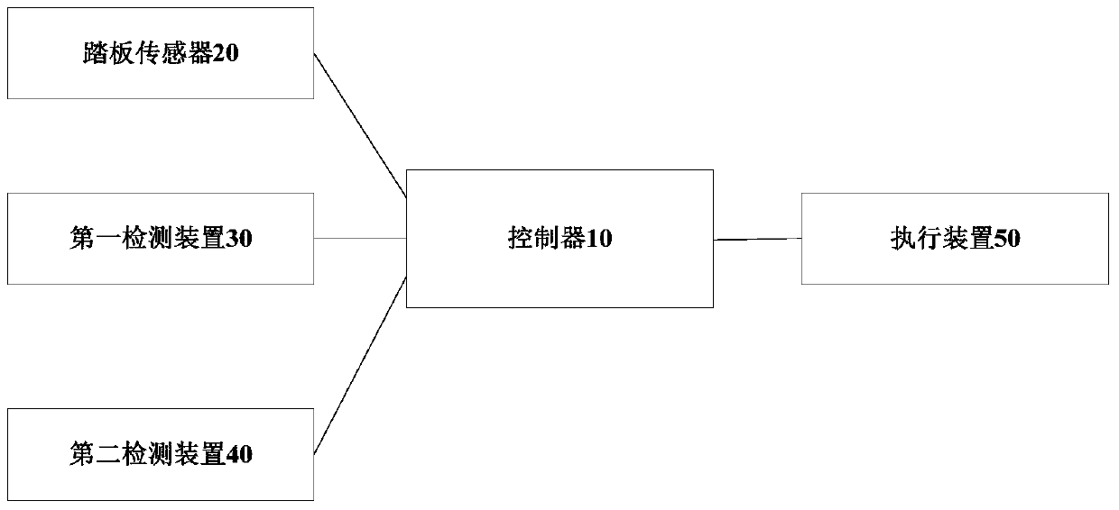
[0042] According to one aspect of the present invention, a vehicle controller is provided, which is grounded on the frame and powered by a battery. Refer to figure 1 As shown, the vehicle controller 10 includes: a power supply module 100, which is used to supply power to the pedal sensor 20, and the pedal sensor 20 is used to detect the pedal depression depth and convert the pedal depression depth into a corresponding pedal voltage signal V pedal ; Acquisition module 101, for collecting the pedal voltage signal V pedal , the voltage signal V of the grounding point between the vehicle controller 10 and the vehicle frame 1 , the negative voltage signal V of the...


PUM


Abstract

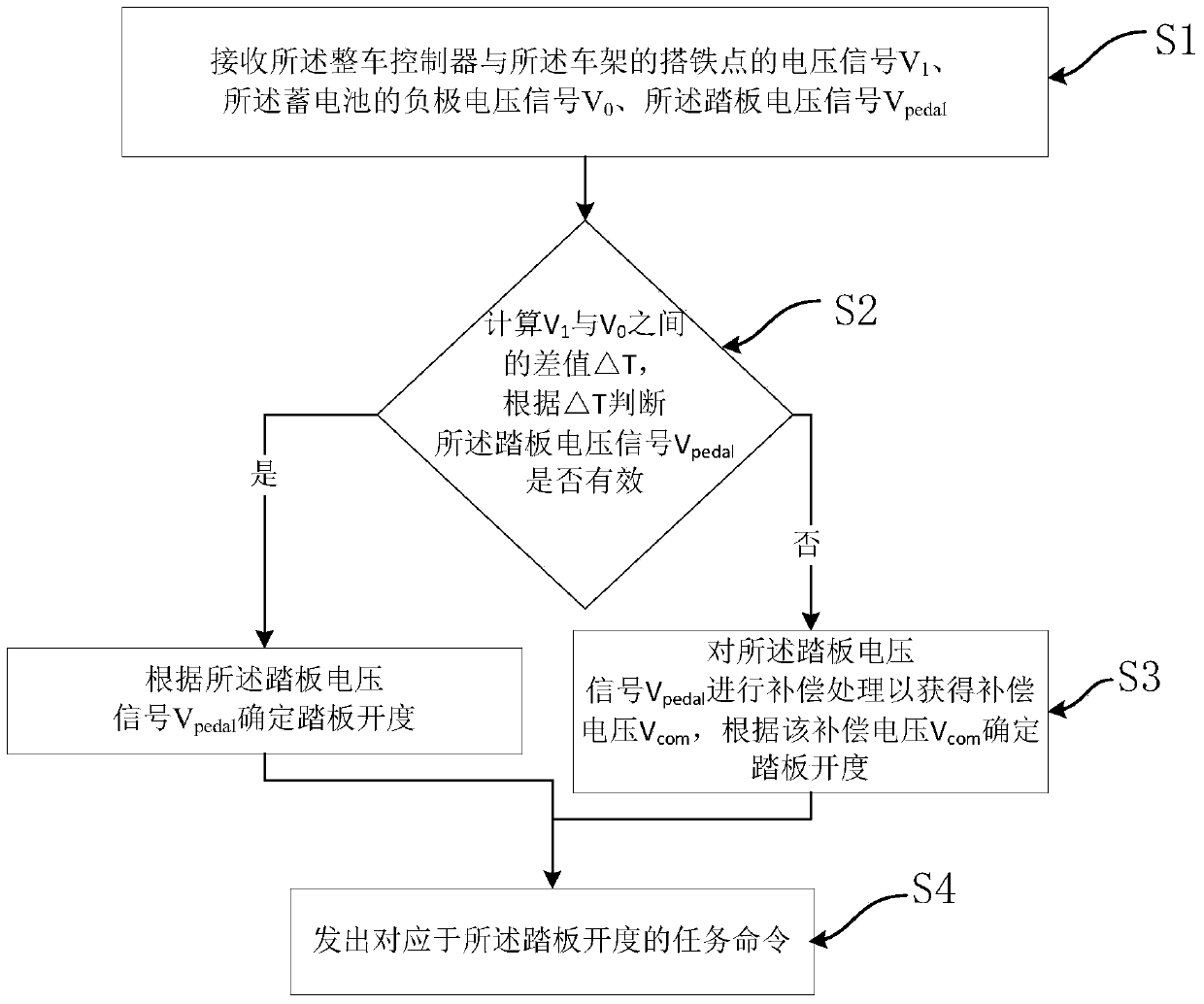
The invention discloses a vehicle controller, a vehicle control system, a vehicle and a pedal signal compensation method. The vehicle controller comprises a power source module used for supplying power to a pedal sensor, a collecting module for collecting the pedal voltage signal Vpedal, the bonding point voltage signal V1 and the storage battery negative electrode voltage signal V0, a judging module for calculating that deltaT=V1+V0 and judging whether the Vpedal is valid or not according to the deltaT, a processing module which enters into a first processing mode when the Vpedal is valid and enters into a second processing mode when the Vpedal is invalid, and a control module for sending out the task instruction corresponding to the opening degree of a pedal. Under the first processing mode, the processing module determines the opening degree of the pedal according to Vpedal; and under the second processing mode, the processing module conducts compensation treatment on Vpedal so as to obtain the compensation voltage Vcom, and the opening degree of the pedal is determined according to Vcom. According to the vehicle controller, the pedal opening degree corresponding to the actual pedal stepped-down depth can be analyzed according to the pedal signal, and the influence of the drift voltage is avoided.

Description

technical field [0001] The invention relates to the technical field of electric vehicles, in particular to a vehicle controller, a vehicle control system, a vehicle and a pedal signal compensation method. Background technique [0002] The Vehicle Management System (i.e., the powertrain controller) is the core control component of the entire vehicle, which collects the driver's driving signals (such as accelerator pedal signals, brake pedal signals, etc.) After the corresponding analysis and judgment, control the action of each component controller in the lower layer to drive the car. The vehicle controller manages, dispatches, analyzes and calculates network information through the CAN (Controller Area Network) bus, and performs corresponding energy management according to different configurations of vehicle models to realize vehicle drive control and energy optimization Functions such as control, brake feedback control, and network management, among which, the analysis of ...

Claims


Application Information

Patent Timeline
Patent Type & Authority Patents(China)
IPC IPC(8): B60R16/023B60K26/02B60T7/04
Inventor 张艳超柴素娟
Owner BORGWARD AUTOMOTIVE CHINA CO LTD
Learn More