
Outer cover support system and method of use

A technology of support system and outer cover plate, which is applied in construction, artificial island, infrastructure engineering and other directions, can solve the problems of bending of outer cover plate 4 and damage of outer cover plate 4, etc., and achieves reduction of shaking strength, convenient operation, Cleverly designed effects

Active Publication Date: 2019-05-03
CCCC HIGHWAY CONSULTANTS
View PDF3 Cites 0 Cited by
  • Summary
  • Abstract
  • Description
  • Claims
  • Application Information

AI Technical Summary

Problems solved by technology

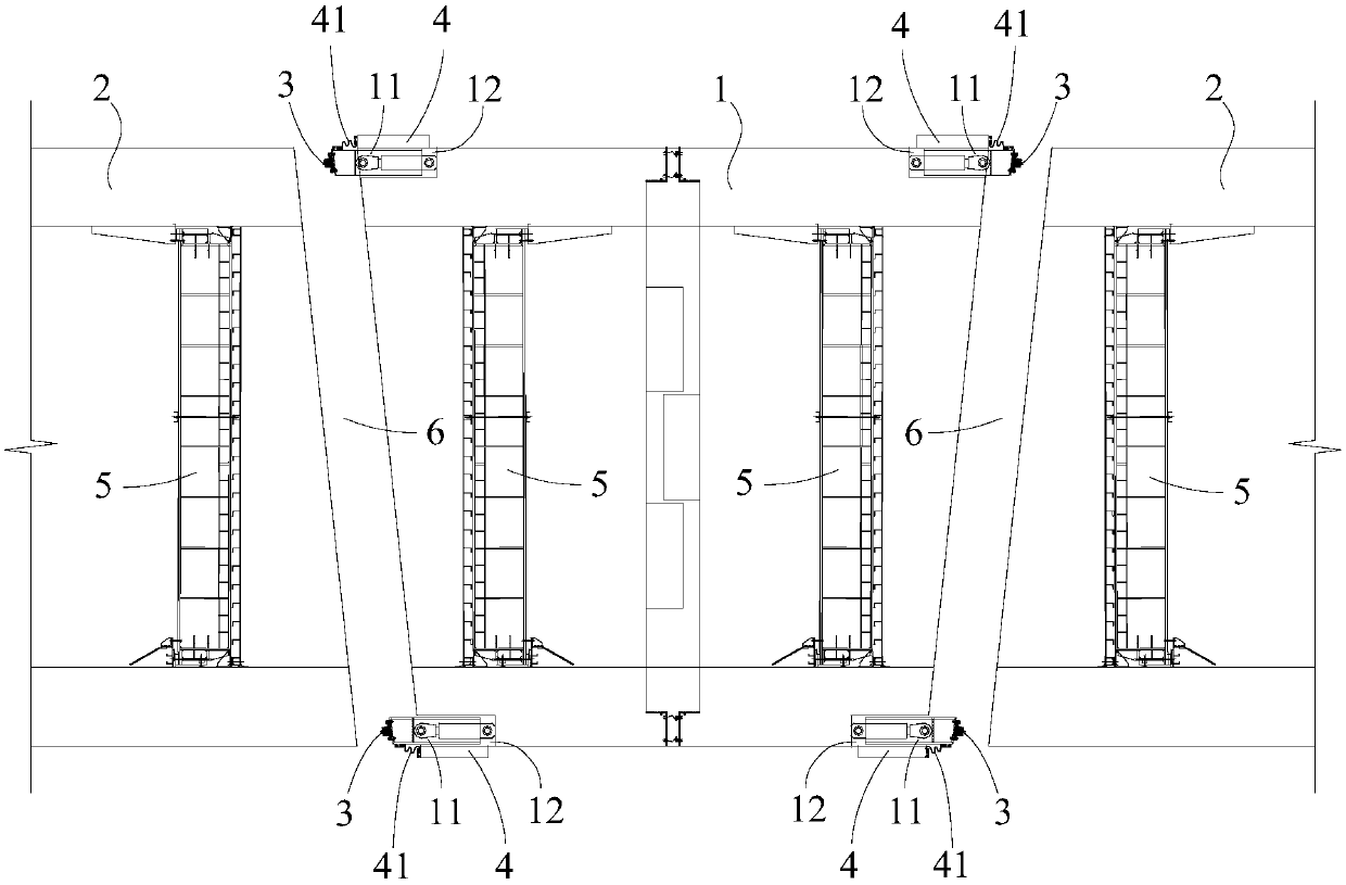
[0003] like figure 1 As shown, the length of the final joint 1 is less than the distance between the two immersed tubes 2 that are docked with it. After the final joint 1 is installed in place, the closed ring-shaped pushing beams 11 respectively provided at both ends of the final joint 1 push and drive the closed ring. Shaped first waterstop 3 is closely attached to the end surface of the immersed tube 2, so that the final joint 1 is docked with the immersed tube 2, and the pushing beam 11 is arranged in the groove 12 at the end of the final joint, and the outer ring of the groove 12 is set There is a closed annular outer cover 4, one end of the outer cover 4 is rigidly connected to the final joint 1 to form a cantilever structure, and the other end of the outer cover 4 is provided with a closed annular second water stop 41, the second stop The water belt 41 is connected to the pushing girder 11, and the second waterstop 41 is used to ensure the waterproof between the slidingly set pushing girder 11 and the final joint 1. After the final joint 1 is docked with the immersed tube 2, the end seal door The water in the joint chamber 6 between 5 is discharged to form a dry construction environment for subsequent construction. At this time, the water pressure outside the pipe joint is greater than the air pressure inside the pipe joint, and the water pressure acts on the outer cover plate 4. Since the outer cover plate 4 has only one end rigid connection, the other end is suspended in the air, which may easily cause the outer cover 4 to bend, and the second waterstop 41 and the end of the outer cover 4 are attached to the push beam 11, which may even cause the structure of the outer cover 4 to be damaged and leak water.

Method used


Image

  • Outer cover support system and method of use
  • Outer cover support system and method of use
  • Outer cover support system and method of use

Examples


Embodiment 1

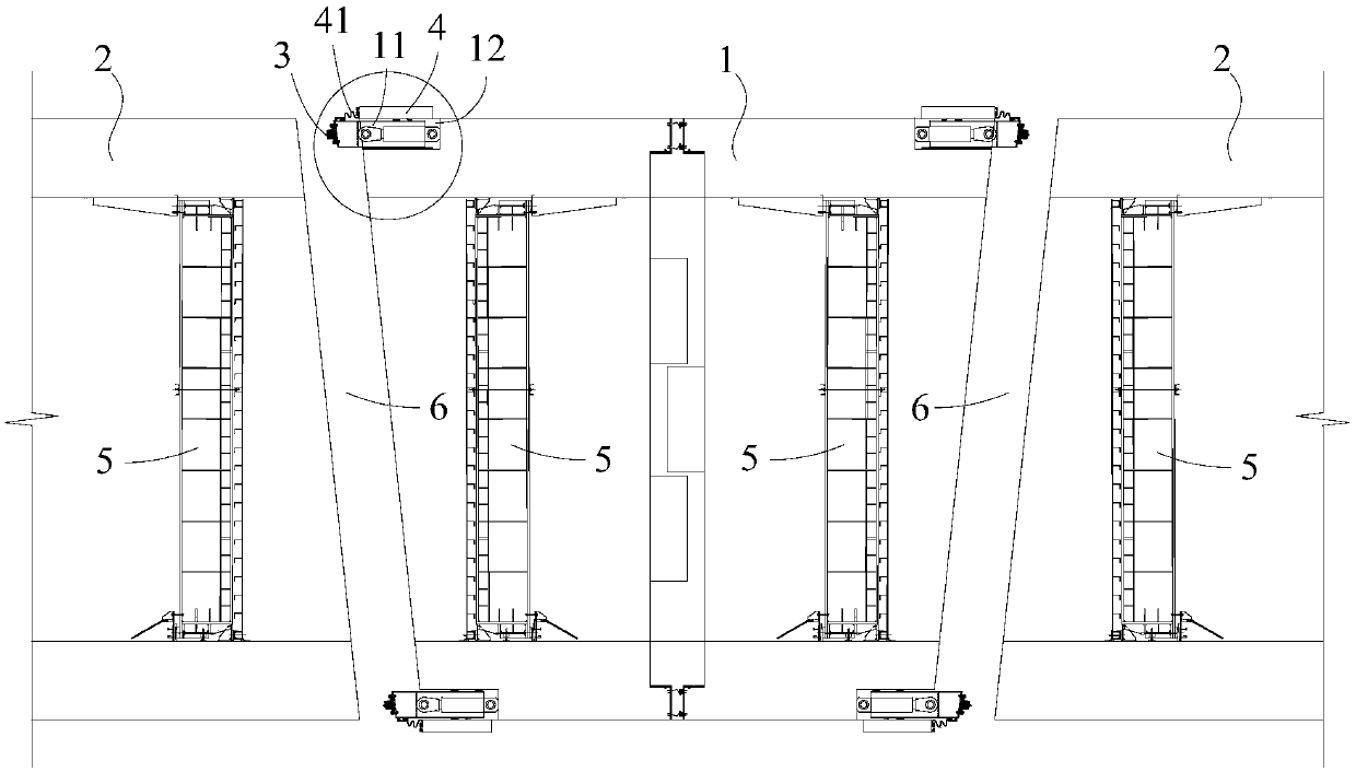
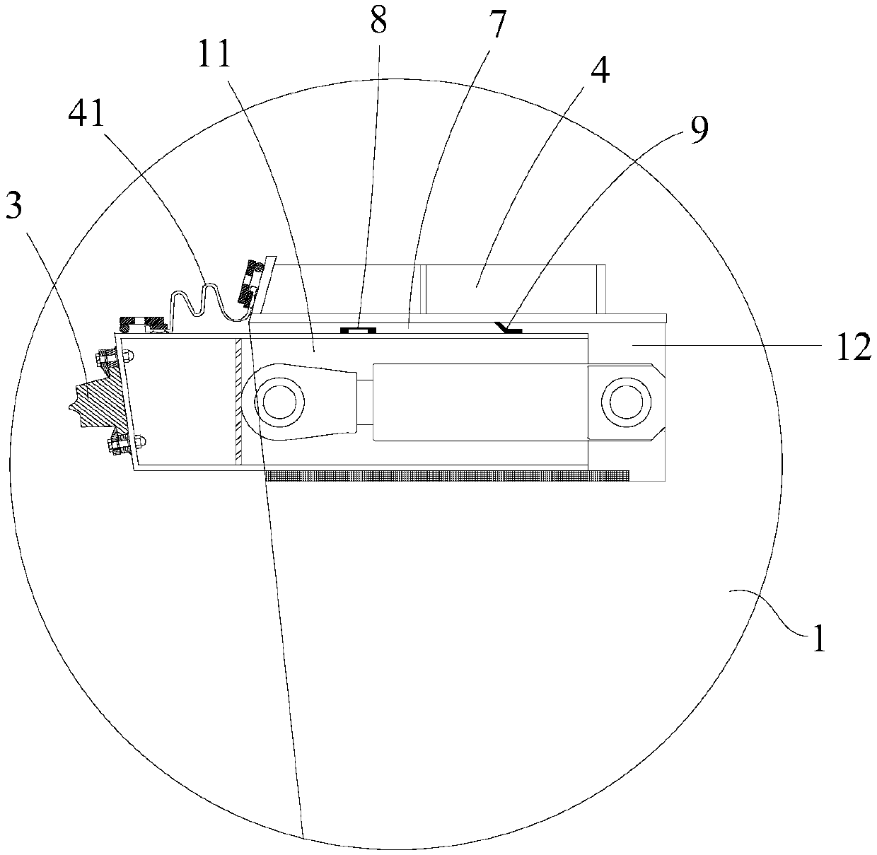
[0040] Such as Figure 1-5 As shown, in an outer cover support system according to the present invention, a plurality of supports 8 are provided in the gap 7 between the closed annular push beam 11 and the closed annular outer cover 4 .

[0041] All the supports 8 are connected to the outer wall of the pushing beam 11 along the circumferential direction of the pushing beam 11, after the pushing beam 11 pushes the first water stop belt 3 to stop the water The support 8 is located at the lower part of the free end of the outer cover plate 4, and the first water stop 3 is a Gina water stop.

[0042] As a preferred solution of this embodiment, all the supports 8 are evenly arranged to balance the external water pressure; The spacing is 1 cm. With this structure, it is ensured that the support 8 does not touch during the sliding process relative to the outer cover plate 4, and the friction force during the movement of the pushing beam 11 is reduced. At the same time, the outer cov...

Embodiment 2

[0048] Such as Figure 1-5 As shown, the method for using an outer cover support system according to the present invention, applying the outer cover support system as described in Embodiment 1, includes the following steps:

[0049] A. After the final joint 1 is placed, adjust its position to align with the immersed tubes 2 on both sides;

[0050] B. The pushing beam 11 moves relative to the final joint 1, and drives the first waterstop 3 to move to the corresponding end surface of the immersed tube 2;

[0051] C. All the supports 8 move with the push beam 11, and move to the free end of the outer cover plate 4;

[0052] D. When the first waterstop 3 is closely attached to the corresponding end surface of the immersed tube 2 , all the supports 8 move to the lower part of the free end of the outer cover plate 4 .

[0053] Using the method of using the outer cover plate support system of the present invention, the support 8 arranged in the gap 7 moves with the pushing beam 11,...


PUM


Abstract

The invention discloses an outer cover plate supporting system. A plurality of supports are arranged in the gap between an enclosed ring-shaped push small beam and an enclosed ring-shaped outer cover plate. All the supports are connected to the outer wall of the push small beam in the circumferential direction of the push small beam. After the push small beam pushes a first water stop belt to stop water, all the supports are located on the lower portion of the suspended end of the outer cover plate. By applying the outer cover plate supporting system, the supports arranged in the gap are moved along with the top small beam, the supports can reduce the swing intensity in the moving process of the push small beam, the supports can be used for supporting the outer cover plate after being moved, a single-point-supported outer cover plate of a cantilever structure is converted to be of a two-point-supported simple support beam structure, the problem that the outer cover plate structure is damaged since the single-point cantilever support is pressed and bent through external water pressure after a connection cavity drains water is avoided, and the outer cover plate supporting system is simple in structure, convenient to use and good in supporting effect.

Description

technical field [0001] The invention relates to the field of immersed tube tunnels, in particular to an outer cover support system and a use method. Background technique [0002] Immersed tube method tunnel construction is to float and transport the prefabricated tunnel caissons in semi-submerged barge or dry dock to the predetermined position for sinking and docking. In order to make the last pipe section sink smoothly, it is necessary to leave a space longer than this pipe section. , the pipe section placed in the remaining distance space is regarded as the final joint, that is, the two ends of the tunnel connection are immersed in the construction of the pipe, and the joint is docked in the sea, and the final closed pipe section is the final joint. The final joint of the immersed tube tunnel is the key to the construction of the immersed tube tunnel, especially in the construction of the ultra-long immersed tube tunnel in the open sea, the construction site operation cond...

Claims


Application Information

Patent Timeline
Patent Type & Authority Patents(China)
IPC IPC(8): E02D29/073
CPCE02D29/073
Inventor 刘晓东李毅林巍邓科程潜刘凌锋
Owner CCCC HIGHWAY CONSULTANTS
Learn More