Air cooling system for helicopter

An air-cooling system and helicopter technology, applied in the field of helicopters, can solve the problems of insufficient cooling effect and cooling stability, and achieve the effects of low production and use costs, light weight, and simple structure

Pending Publication Date: 2017-12-19
湖南省库塔科技有限公司
View PDF6 Cites 0 Cited by
  • Summary
  • Abstract
  • Description
  • Claims
  • Application Information

AI Technical Summary

Problems solved by technology

[0004] Most of the current helicopter engine cooling adopts natural air cooling, and the engine is cooled by the downpressure wind generated by the rotor and natural wind. This cooling method is greatly affected by the environment, and the cooling effect and cooling stability are insufficient.

Method used


Image

  • Air cooling system for helicopter
  • Air cooling system for helicopter
  • Air cooling system for helicopter

Examples


Embodiment Construction

[0025] In order to enable those skilled in the art to better understand the technical solutions in the present application, the technical solutions in the embodiments of the present application will be clearly and completely described below in conjunction with the drawings in the embodiments of the present application. Obviously, the described The embodiments are only some of the embodiments of the present application, but not all of them. Based on the embodiments in this application, all other embodiments obtained by persons of ordinary skill in the art without creative efforts shall fall within the scope of protection of this application.

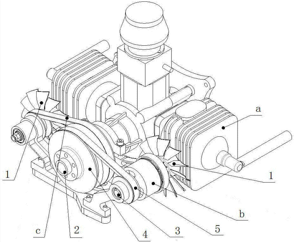
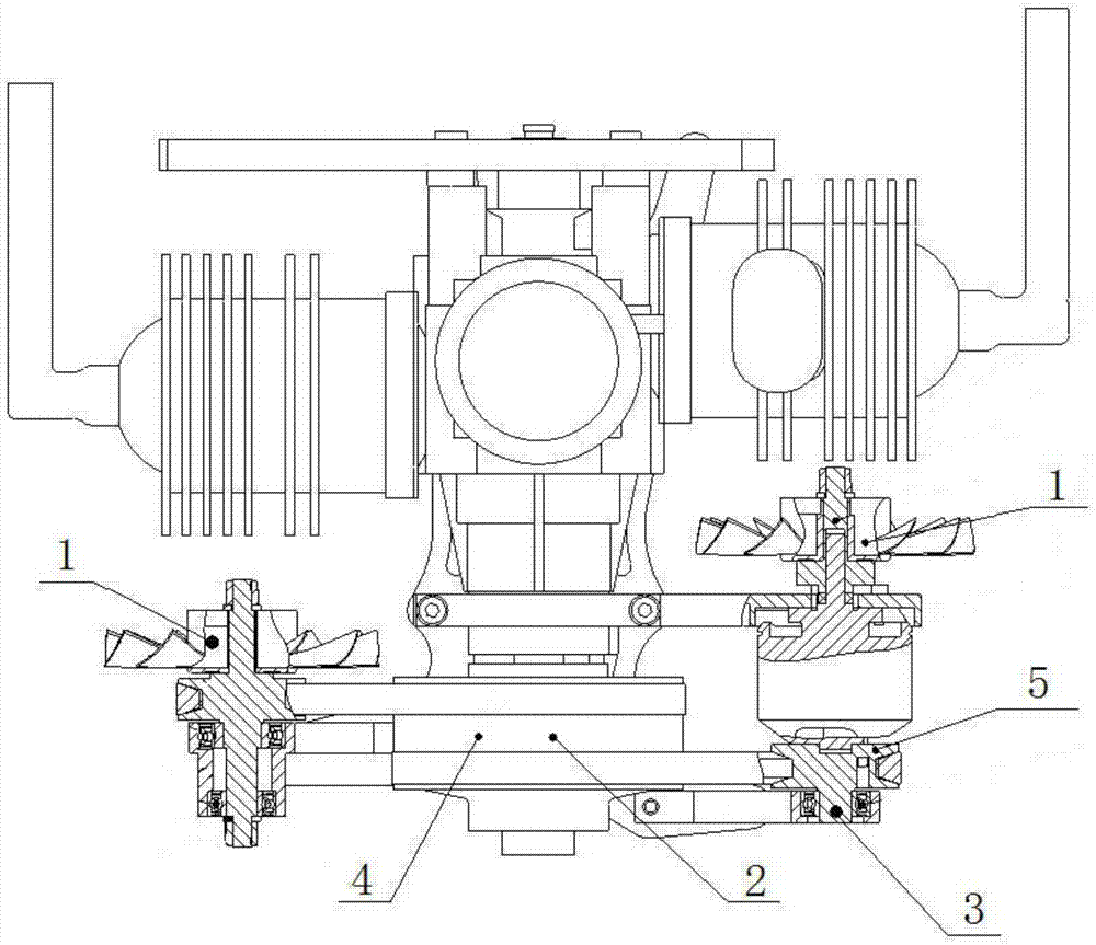
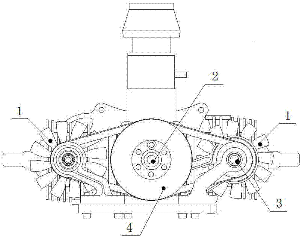
[0026] please if Figure 1 to Figure 3 As shown, the embodiment of the present invention provides an air cooling system for a helicopter, including a fan 1, the shaft of the fan 1 is connected with the engine output end 2, and the engine output end 2 rotates to drive the fan 1 to rotate .

[0027] When the UAV is working continuously, t...


PUM


Abstract

The invention discloses an air cooling system for a helicopter. The air cooling system comprises a fan (1), wherein the shaft of the fan (1) is in belt connection with an engine output end (2), and the engine output end (2) rotates to drive the fan (1) to rotate. The air cooling system is suitable for being installed in a narrow space in an unmanned aerial vehicle, the structure is compact, the shape of the unmanned aerial vehicle does not need to be changed, and the air cooling system can adapt to engine cooling requirements of unmanned aerial vehicles of various models.

Description

technical field [0001] The present application relates to the technical field of helicopters, in particular to an air cooling system for helicopters. Background technique [0002] Unmanned aircraft, referred to as "UAV", is an unmanned aircraft controlled by radio remote control equipment and its own program control device. Compared with manned aircraft, drones have the advantages of small size, low cost, convenient use, and low environmental requirements. They are widely used in aerial photography, agriculture, plant protection, miniature selfies, express transportation, disaster relief, observing wild animals, Infectious diseases, surveying and mapping, news reports, power inspection, disaster relief and other fields. [0003] When the UAV works continuously, the temperature of the engine cylinder is too high, which will reduce the engine power, cause serious carbon deposits, premature combustion, deflagration, and changes in the structural properties of the cylinder mate...

Claims


Application Information

Patent Timeline
IPC IPC(8): F01P5/04F02B63/06F02B61/06F02B63/04B64D33/08
CPCF01P5/04F02B61/06F02B63/04F02B63/06B64D33/08
Inventor 李均
Owner 湖南省库塔科技有限公司
Why Eureka
Try Eureka