
Steel frame platform

A platform and steel frame technology, which is applied to the accessories of scaffolding, formwork/formwork/work frame, and on-site preparation of building components, etc. Highly adjustable and easy to operate

Active Publication Date: 2017-12-22
ZHEJIANG QIAOXING CONSTR GRP
View PDF5 Cites 1 Cited by
  • Summary
  • Abstract
  • Description
  • Claims
  • Application Information

AI Technical Summary

Problems solved by technology

[0002] The existing building formwork platform (especially the climbing formwork platform) is closed with a flap between the bottom layer and the wall to prevent falling objects. The flap is simply a flat plate hinged on the platform, and the flap between the flaps There is no connection between them, and it is easy to flip. Because the flap is a hard board structure, it is more laborious to turn it up. It is inconvenient to turn and it is easy to stick your hands.

Method used


Image

  • Steel frame platform
  • Steel frame platform
  • Steel frame platform

Examples


Embodiment 1

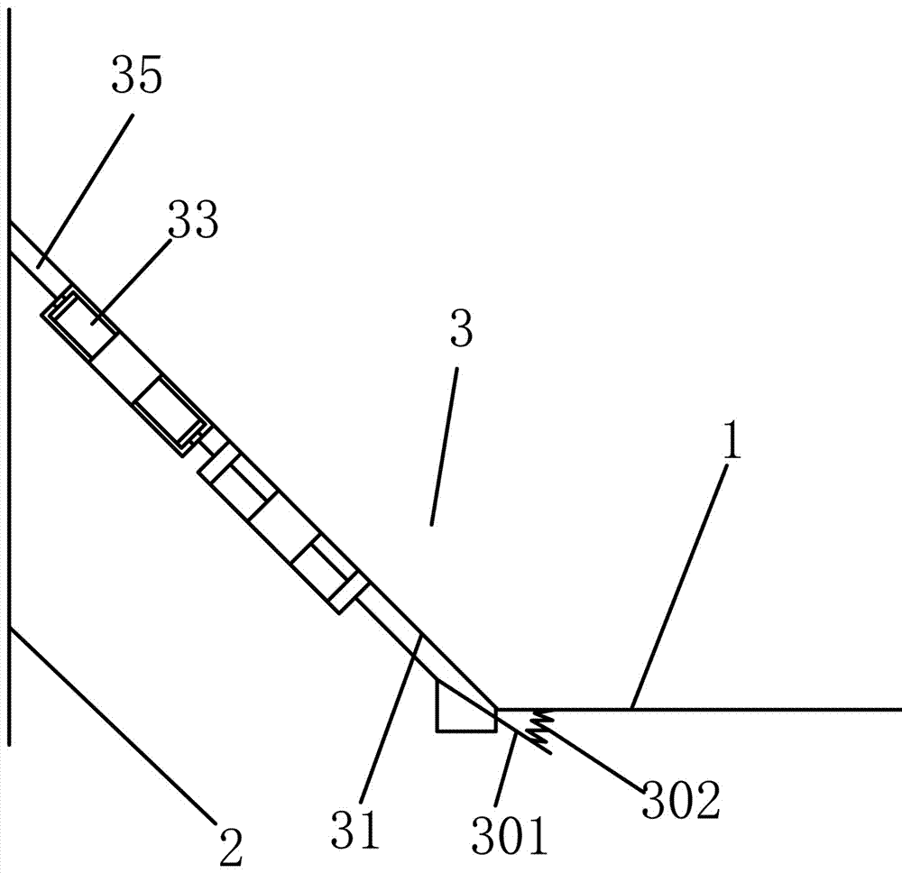
[0034] A steel frame platform, comprising a platform body 1, a plurality of flaps 3 hinged end-to-end to the edge of the platform body close to the wall 2, and an extension plate 10 detachably connected to the flap, the The flap includes a plate body 31, a lifting connecting piece that is arranged on both sides of the middle and upper part of the plate body and can be buckled with an adjacent plate body, and the lifting connecting piece includes a The open slot 32 is hinged on the notch of the slot and can be turned outward to the lifting handle 33 on the adjacent board through the hinge point; the middle part of the board is sunken to form a guide groove 35, and the guide groove is triangular. And near the end that the plate body is connected with the platform body is a narrowing part 351, and the end far away from the platform body is an expanding part 352, and the bottom of the narrowing part is concave to form the ash accumulation tank 9, and the ash accumulation tank is de...

Embodiment 2

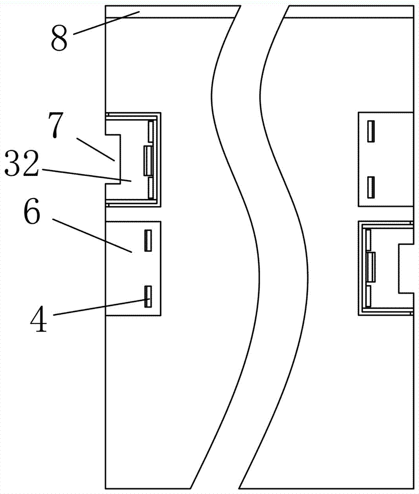
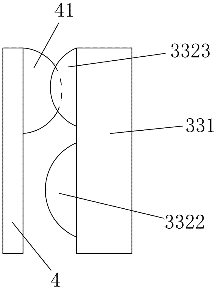
[0042] The difference from the above-mentioned embodiment is that a receiving groove 6 is opened on the adjacent plate body corresponding to the embedding groove, and a buckle plate 4 is arranged in the receiving groove corresponding to the position of the handle, and the convex wave part and the The shape of the hands of the card is the same; on the same side of the same board, an embedding groove and a receiving groove are sequentially arranged up and down, and on the other side, an accepting groove and an embedding groove are sequentially arranged up and down.

[0043] The receiving groove and the embedding groove are used to cooperate with the lifting handle to ensure that the lifting handle does not protrude from the board body, the flap and the platform can fit together, and at the same time can buckle the lifting handle, and can make the gap between adjacent flaps to connect.

Embodiment 3

[0045]The difference from the above-mentioned embodiment is that there is a lifting plate notch 7 on the bottom plate of the groove where the embedding groove is located at the notch position. The edge of the notch of the lifting plate is covered with a rubber skin 71 . At least the upper edge of the board is covered with a rubber strip 8 .

[0046] The rubber skin ensures that it is not easy to cut hands when holding it, and it is easy to flip the flap. The rubber strip has an anti-collision effect and can also protect the platform, board and wall.


PUM


Abstract

The invention belongs to the field of architecture, and particularly relates to a steel frame platform. The platform comprises a platform body, multiple end-to-end turning plates which are connected to the edge of the side, close to a wall, of the platform body in a hinged mode and extension plates which are detachably connected to the turning plates, each turning plate comprises a plate body and pulling connectors which are arranged on both sides of the middle-upper portion of each plate body and connected with the adjacent plate bodies in a clipping mode, and each pulling connector comprises an embedding groove which is formed in each plate body and has an opening formed in the side toward the adjacent plate body and a pulling handle which is connected into the opening of each embedding groove in a hinged mode and can turn outward to the adjacent plate body through a hinging point. According to the platform, the adjacent plate bodies can be in clipping connection, which are not likely to be turned; the pulling handle are embedded in the plate bodies, and when the plate bodies cover the platform body, it is guaranteed that the plate bodies are attached to the platform body, so that normal passing is guaranteed; when the turning plates are needed to be turned, the embedding grooves are pulled through embedded pulling plate notches, so that the turning plates are pulled up; operation is convenient and safe.

Description

technical field [0001] The invention belongs to the field of construction, and in particular relates to a steel frame platform. Background technique [0002] The existing building formwork platform (especially the climbing formwork platform) is closed with a flap between the bottom layer and the wall to prevent falling objects. The flap is simply a flat plate hinged on the platform, and the flap between the flaps There is no connection between them, and it is easy to flip. Because the flap is a hard board structure, it is more laborious to turn it up. It is inconvenient to flip and easy to stick. It is also easy to make harsh noises when flipped. And most of the existing flaps are of uniform specifications, but for building exterior walls of different structures, the distance between the platform and the exterior walls is different. Contents of the invention [0003] The object of the present invention is to provide a steel frame platform for the above problems. [0004]...

Claims


Application Information

Patent Timeline
Patent Type & Authority Applications(China)
IPC IPC(8): E04G11/20E04G5/00
CPCE04G5/001E04G11/20
Inventor 丁忠良杨奇钱法荣马根宝潘兰兰杨怀金
Owner ZHEJIANG QIAOXING CONSTR GRP
Learn More