
A deformation monitoring method for timely alarming in dangerous areas

A deformation monitoring, hazardous area technology, applied in measurement devices, radio wave measurement systems, reflection/re-radiation of radio waves, etc., to achieve the effect of easy identification

Active Publication Date: 2019-10-01
安徽威德萨科技有限公司
View PDF4 Cites 0 Cited by
  • Summary
  • Abstract
  • Description
  • Claims
  • Application Information

AI Technical Summary

Problems solved by technology

[0006] The purpose of the present invention is to overcome the deficiency that it is difficult to make timely disaster forecasts in dangerous areas in the existing deformation monitoring methods, and to provide a deformation monitoring method for timely alarming in dangerous areas, which can quickly and accurately obtain relatively large deformation variables in SAR displacement maps. The actual location corresponding to the large point, timely make disaster forecasts in dangerous areas

Method used


Image

  • A deformation monitoring method for timely alarming in dangerous areas
  • A deformation monitoring method for timely alarming in dangerous areas
  • A deformation monitoring method for timely alarming in dangerous areas

Examples


Embodiment 1

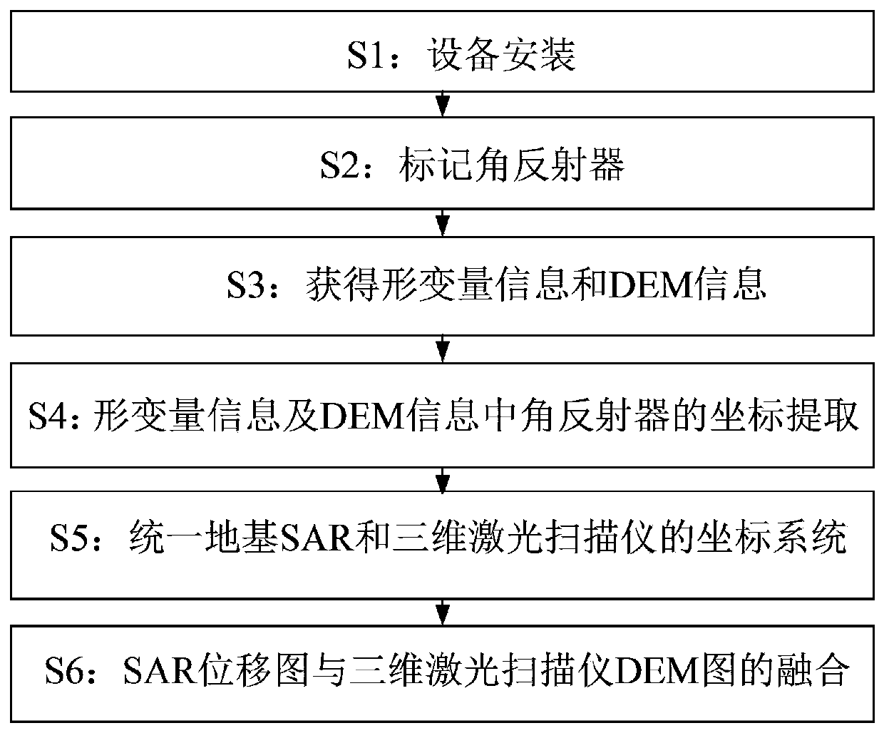
[0038] combinefigure 1 , the deformation monitoring method of the dangerous area of ​​the present embodiment alarming in time, comprises the following steps:

[0039] S1: equipment installation;

[0040] In S1: Select a suitable monitoring area, and deploy ground-based SAR, 3D laser scanners and corner reflectors in the monitoring area, and install GPS receivers on the corner reflectors. Among them, the corner reflectors in the monitoring area need to be arranged at equal intervals; and the layout points of the ground-based SAR and the 3D laser scanner need to be inspected on the spot, and a suitable location should be selected for deployment, so that the line of sight of the two devices can cover the monitoring area well, and Keep the monitoring area consistent. In addition, the monitored area is required to have a certain typical terrain (such as dam monitoring, landslide monitoring, etc.), which is convenient for the extraction of deformation information and DEM informatio...


PUM


Abstract

The invention discloses a deformation monitoring method realizing timely alarm for a danger area, which relates to the field of deformation monitoring of dams, slopes, bridges, railways, highways and hillsides. The method includes the following steps: S1, installing equipment; S2, marking corner reflectors; S3, obtaining foundation SAR deformation information and laser scanner DEM information; S4, extracting the coordinates of the corner reflectors from the foundation SAR deformation information and DEM information; S5, unifying the coordinate systems of foundation SARs and 3D laser scanners; and S6, fusing a foundation SAR deformation displacement diagram and a 3D laser scanner DEM diagram. The invention aims to overcome the problem that it is difficult to predict the disaster in a danger area through the existing deformation monitoring method, and provides a deformation monitoring method realizing timely alarm for a danger area. Through the deformation monitoring method of the invention, the actual positions corresponding to largely deformed points in the foundation SAR displacement diagram can be acquired quickly and accurately, and the disaster in a danger area can be predicted in time.

Description

technical field [0001] The invention relates to the field of deformation monitoring of dams, slopes, bridges, railways, highways, hillsides, etc., and more specifically relates to a deformation monitoring method for timely alarming in dangerous areas. Background technique [0002] In recent years, deformation monitoring of dams, landslides, bridges, railways, etc. has become more and more important. At present, the more common deformation monitoring method is to use ground-based SAR to obtain the deformation of the monitoring target. The ground-based SAR technology synthesizes the azimuth aperture through the reciprocating movement of the antenna on the horizontal guide rail. By acquiring images of the target area at different times, and using DInSAR technology to obtain submillimeter-level deformation and displacement accuracy, it is mainly used for landslides, glaciers, dams, bridges , railways and other deformation monitoring, analyze the deformation trend and make timely...

Claims


Application Information

Patent Timeline
Patent Type & Authority Patents(China)
IPC IPC(8): G01B11/16G01S13/90G01S13/08
CPCG01B11/16G01S13/08G01S13/90G01S13/9023
Inventor 窄秋苹张昊宇黄勇王佑实王超陈力
Owner 安徽威德萨科技有限公司
Learn More