Method for Improving Imaging Quality of Off-Axis Three-mirror Optical System

An optical system, off-axis three-mirror technology, applied in the direction of optics, optical components, instruments, etc., can solve the problems of optical component position error, asymmetry, missing part of the central optical axis of the mirror, etc., to reduce the impact and improve quality effect

Inactive Publication Date: 2020-07-24
TIANJIN UNIV
View PDF4 Cites 0 Cited by
  • Summary
  • Abstract
  • Description
  • Claims
  • Application Information

AI Technical Summary

Problems solved by technology

Due to the large number of mirrors in the off-axis three-mirror system, the absence of the central optical axis of each mirror, and the off-axis and asymmetry of the optical structure, it is very difficult to assemble the system
At present, the method of combining initial positioning and computer-aided adjustment is mainly used. The assembly process will bring position errors of optical components, which will change the imaging axis of the system, generate imaging positioning errors, and reduce the imaging accuracy and quality of the camera.

Method used


Image

  • Method for Improving Imaging Quality of Off-Axis Three-mirror Optical System
  • Method for Improving Imaging Quality of Off-Axis Three-mirror Optical System
  • Method for Improving Imaging Quality of Off-Axis Three-mirror Optical System

Examples


Embodiment Construction

[0047] The technical problem of the present invention is: a theoretical research method for the relationship between the position change of the visual axis of an off-axis three-mirror optical system and the imaging position of the system. The imaging position compensation of the off-axis three-mirror optical system can be realized, and the imaging quality of the system can be improved.

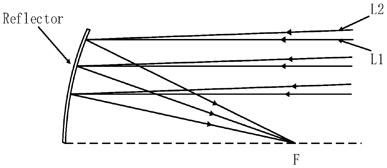
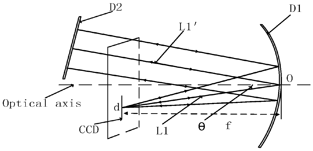
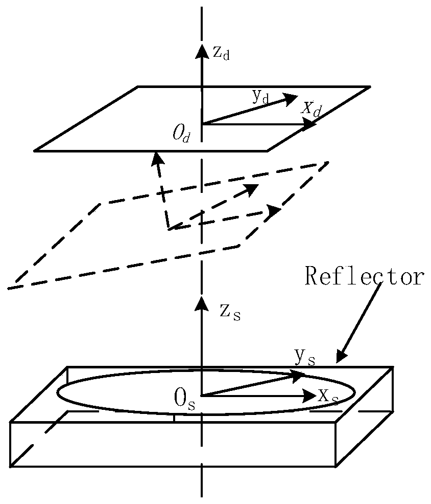
[0048] The technical scheme of the present invention is as follows: theoretically analyze the influence of the change of the visual axis on the imaging of the system, because the imaging optical path of the off-axis three-mirror optical system is complicated, the present invention proposes to equate the off-axis three-mirror system to a single-reflection system, and establish a reference mirror Imaging model, using equivalent and coordinate conversion mathematical methods to theoretically derive imaging formulas. The point light source passes through the reflector D1 and the reference reflecto...


PUM


Abstract

The present invention relates to the imaging theory of an optical system. In order to compensate the imaging position of an off-axis three-mirror optical system and improve the imaging quality of the system, the technical scheme adopted in the invention is a method for improving the imaging quality of an off-axis three-mirror optical system, which equates the off-axis three-mirror system to a single reflection system. The method establishes an imaging model with a reference mirror, and uses a mathematical method of equivalent and coordinate conversion to theoretically deriving an imaging formula, wherein a point light source passes through a mirror D1 and a reference mirror D2, a point r is converged on a CCD of a focal plane, a mirror center Os is taken as the origin to establish an ideal coordinate system OsXsYsZs, the Zs axis and the sight axis are in the same line, an actual imaging coordinate system OrXrYrZr is established with the actual CCD center Or as the origin. The method of imaging coordinate compensation considers only the optical axis rotation translation and the focal length change while ignoring optical distortion errors. The method is mainly applied to the imaging detection occasions of the optical system.

Description

technical field [0001] The invention relates to an imaging theory of an optical system, and relates to a theoretical analysis of the position change of the visual axis of an off-axis three-mirror optical system and the imaging quality of the system. Specifically, it relates to a method for improving the imaging quality of an off-axis three-mirror optical system. Background technique [0002] The off-axis three-mirror optical system does not produce chromatic aberration, has no secondary spectrum, uses a wide band, can make the aperture large, and is easy to reduce weight. The three-mirror can obtain a larger field of view, and it is easy to control the stray radiation of the optical system. At the same time, because the off-axis system has no central obstruction, the luminous flux entering the optical system is relatively large, which makes the image plane illumination more uniform and high-resolution imaging, which can meet the requirements and development direction of the ...

Claims


Application Information

Patent Timeline
Patent Type & Authority Patents(China)
IPC IPC(8): G02B17/06G02B27/00
CPCG02B17/0626G02B27/0012
Inventor 李杏华张冬高凌妤郭倩蕊景泉胡震岳
Owner TIANJIN UNIV
Why Eureka
Try Eureka