
Self-aligned super-junction structure and preparation method thereof

A self-alignment and doping type technology, applied in the direction of electrical components, circuits, semiconductor devices, etc., can solve the problems of relatively large fluctuations in final product parameters, strict control requirements, and low process compatibility, and achieve high stability of product parameters , good process compatibility and wide process specifications

Active Publication Date: 2017-12-22
CHINA RESOURCES MICROELECTRONICS (CHONGQING) CO LTD
View PDF3 Cites 3 Cited by
  • Summary
  • Abstract
  • Description
  • Claims
  • Application Information

AI Technical Summary

Problems solved by technology

However, the control requirements for the above key parameters are strict, the process is difficult and the process compatibility is small, so that the parameters of the final product fluctuate relatively large

Method used


Image

  • Self-aligned super-junction structure and preparation method thereof
  • Self-aligned super-junction structure and preparation method thereof
  • Self-aligned super-junction structure and preparation method thereof

Examples


Embodiment 1

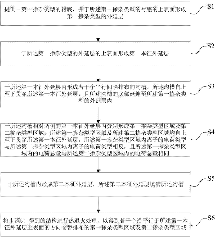
[0046] see figure 1 , this embodiment provides a method for preparing a self-aligned super-junction structure, the method for preparing a self-aligned super-junction structure includes the following steps:

[0047] 1) providing a substrate of the first doping type, and forming an epitaxial layer of the first doping type on the upper surface of the substrate of the first doping type;

[0048] 2) forming a first intrinsic epitaxial layer on the upper surface of the epitaxial layer of the first doping type;

[0049] 3) Forming several trenches arranged in parallel at intervals in the first intrinsic epitaxial layer, the trenches penetrate the first intrinsic epitaxial layer from top to bottom, and the bottoms of the trenches extend to In the epitaxial layer of the first doping type;

[0050]4) A first doping type region and a second doping type region are respectively formed in the first intrinsic epitaxial layer on opposite sides of the trench, and the first doping type region...

Embodiment 2

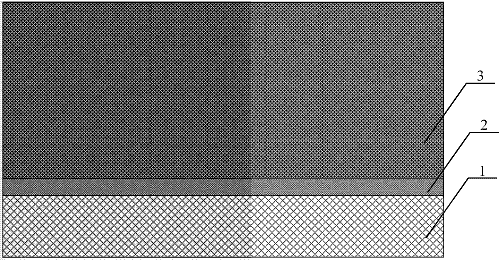
[0086] read on Figure 1 to Figure 10 , this embodiment provides a self-aligned super-junction structure, and the self-aligned super-junction structure is prepared by the preparation method described in Embodiment 1.

[0087]In summary, the self-aligned superjunction structure and its preparation method of the present invention include the following steps: 1) providing a substrate of the first doping type, and forming a substrate on the substrate of the first doping type Forming an epitaxial layer of the first doping type on the surface; 2) forming a first intrinsic epitaxial layer on the upper surface of the epitaxial layer of the first doping type; 3) forming several epitaxial layers in the first intrinsic epitaxial layer trenches arranged in parallel at intervals, the trenches penetrate the first intrinsic epitaxial layer from top to bottom; 4) forming first doped type region and the second doping type region, the first doping type region and the second doping type region ...


PUM


Abstract

The invention provides a self-aligned super-junction structure and a preparation method thereof. The method comprises the steps that 1) a substrate of a first doping type is provided, and an epitaxial layer of the first doping type is formed on the upper surface of the substrate of the first doping type; 2) first intrinsic epitaxial layers are formed on the upper surface of the epitaxial layer of the first doping type; 3) a number of parallel spaced trenches are formed in the first intrinsic epitaxial layers; 4) a region of the first doping type and a region of a second doping type are respectively formed in first intrinsic epitaxial layers on two opposite sides of each trench; 5) second intrinsic epitaxial layers are formed in the trenches; and 6) ) the structure acquired in the step 5) is subjected to thermal annealing treatment. Compared with the prior art, the preparation method provided by the invention has the advantages of low requirement on the trench line width, wide process specification, good process compatibility, high product parameter stability, low manufacturing cost and the like.

Description

technical field [0001] The invention relates to the technical field of semiconductor structures, in particular to a self-aligned superjunction structure and a preparation method thereof. Background technique [0002] The Super Junction structure uses an alternate PN junction structure instead of a single conductivity type material as the drift region, and a lateral electric field is introduced in the drift region, so that the device drift region can be completely depleted at a small turn-off voltage, breakdown The voltage is only related to the thickness of the depletion layer and the critical electric field. Therefore, under the same withstand voltage condition, the doping concentration of the drift region of the super-junction structure can be increased by an order of magnitude, which greatly reduces the on-resistance. [0003] The key to the high breakdown voltage of the superjunction structure lies in the charge balance between the P region and the N region. When the ch...

Claims


Application Information

Patent Timeline
Patent Type & Authority Applications(China)
IPC IPC(8): H01L29/06
CPCH01L29/0634
Inventor 王代利
Owner CHINA RESOURCES MICROELECTRONICS (CHONGQING) CO LTD
Learn More