Eureka AIR delivers breakthrough ideas for toughest innovation challenges, trusted by R&D personnel around the world.

Phase noise compensation for interferometric absolute distance measuring

A technology of absolute distance and distance, applied in the field of computer program products, capable of solving complex problems

Active Publication Date: 2010-04-14
LEICA GEOSYSTEMS AG
View PDF10 Cites 0 Cited by
  • Summary
  • Abstract
  • Description
  • Claims
  • Application Information

AI Technical Summary

Problems solved by technology

For this, the system is more complex due to the presence of two laser sources, although the structural stability of the interferometer, as well as the stability of the distance to the target, is less demanding

Method used


Image

  • Phase noise compensation for interferometric absolute distance measuring
  • Phase noise compensation for interferometric absolute distance measuring
  • Phase noise compensation for interferometric absolute distance measuring

Examples


Embodiment Construction

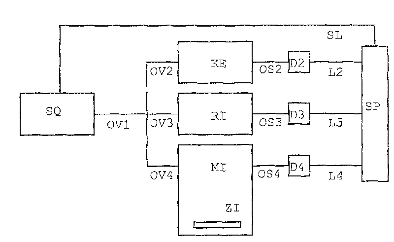
[0072] figure 1 Represents the underlying measurement construct. Signal source SQ is coupled in via optical connectors OV1-OV4 to measuring interferometer MI, reference interferometer RI and optional component calibration unit KE. The target ZI to be measured is an integral part of the measurement interferometer in the measurement. Via optical paths OS2, OS3 and OS4, the signals are transmitted to detector units D2, D3 and D4. The detector signals are sent to the signal processor SP via cables L2, L3 and L4. The signal processor SP is responsible for processing and analyzing the signal and also controls the signal source SQ via the control line SL.

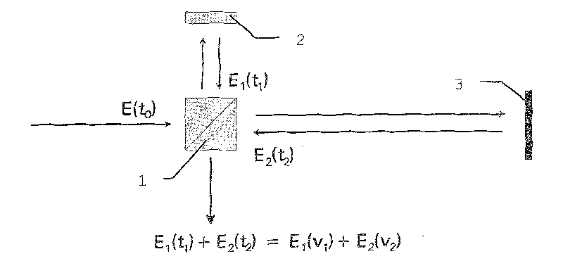
[0073] figure 2 A schematic diagram of the interferometer used to form the heterodyne mixing product is shown. Part of the emitted light is coupled out by the beam splitter 1 , reflected on the reflector 2 and passed through the beam splitter, and superimposed with the light signal scattered back from the reflector 3 . For ...


PUM


Abstract

The invention relates to a method for interferometric absolute distance measuring by a frequency modulation electromagnetic radiation on at least one measurable target and for subsequently receiving aretransmitted radiation with a heterodyne mixture, wherein the radiation is guided in a parallel direction via a reference interferometric length. In such a way, a first digitised interferogram of theradiation retransmitted by the target and a second digitised interferogram of the radiation guided on the reference length are obtainable at a reception. According to phase progression data of the se cond interferogram, a virtual interferogram or a phase progression thereof is synthesised and the distance determination is carried out by comparing the progression face data of the first interferogram with the progression face data of the virtual interferogram.

Description

technical field [0001] The invention relates to an absolute distance measuring method according to the preamble of claim 1 , an absolute distance measuring device according to the preamble of claim 13 , and a computer program product. Background technique [0002] In the field of electronic ranging, various principles and methods are disclosed. One approach is to direct frequency-modulated electromagnetic radiation (such as light) at the target to be measured, and then receive one or more reflected signals from a back-scattering object, ideally only from the target. Here, the target to be measured may not only have specular backscattering characteristics such as mirror characteristics, but also have backscattering characteristics. In a heterodyne interferometer configuration, a tunable laser source is used for absolute distance measurement. In the simplest embodiment in principle, the optical frequency of the laser source is linearly tunable. The received signal is superi...

Claims


Application Information

Patent Timeline
Patent Type & Authority Patents(China)
IPC IPC(8): G01B9/02
CPCG01B2290/30G01B2290/60G01B9/02004G01B9/0207G01B9/02
Inventor 马塞尔·罗纳托马斯·延森
Owner LEICA GEOSYSTEMS AG
Why Eureka
Eureka Blog
Learn More