Combined fish tank

A combined fish tank technology, which is applied in the field of fish tanks and combined fish tanks, can solve problems affecting the practicability of flower pots, and achieve the effects of improving work stability, improving practicability and reducing costs

Inactive Publication Date: 2017-12-26
南京卓策知识产权服务有限公司
View PDF1 Cites 0 Cited by
  • Summary
  • Abstract
  • Description
  • Claims
  • Application Information

AI Technical Summary

Problems solved by technology

But there is a problem in this flowerpot: the size of the cavity that is used to raise fish is fixed, causes this flowerpot to only be used for breeding the fish of specific quantity or the fish of specific size, affects the practicability of this flowerpot

Method used


Image

  • Combined fish tank
  • Combined fish tank

Examples


Embodiment 1

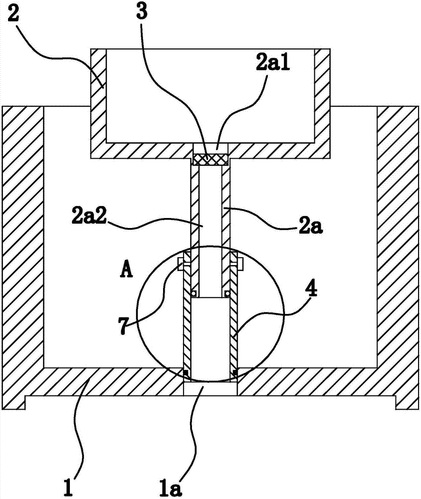
[0025] Such as figure 1 Shown, this combined fish tank is made up of cylinder body 1, flower pot 2, filter screen 3, drainpipe 4 etc. Wherein, the cylinder body 1 is made of transparent glass material.

[0026] Specifically, the cylinder body 1 is open at the top and closed at the bottom; The top of the flowerpot 2 is open, and the bottom of the flowerpot 2 has a cylindrical protruding water-permeable part 2a. The water-permeable part 2a and the flowerpot 2 are integrally structured, and the inner cavities of the two are communicated. The filter screen 3 is arranged in the permeable part 2a, and the filter screen 3 divides the inner cavity of the permeable part 2a into an upper cavity 2a1 and a lower cavity 2a2, wherein the upper cavity 2a1 communicates with the inner cavity of the flowerpot 2; the upper cavity 2a1 and the lower cavity The cavities 2 a 2 communicate through the meshes of the filter 3 . In this example, if figure 1 As shown, there is an annular step on the...

Embodiment 2

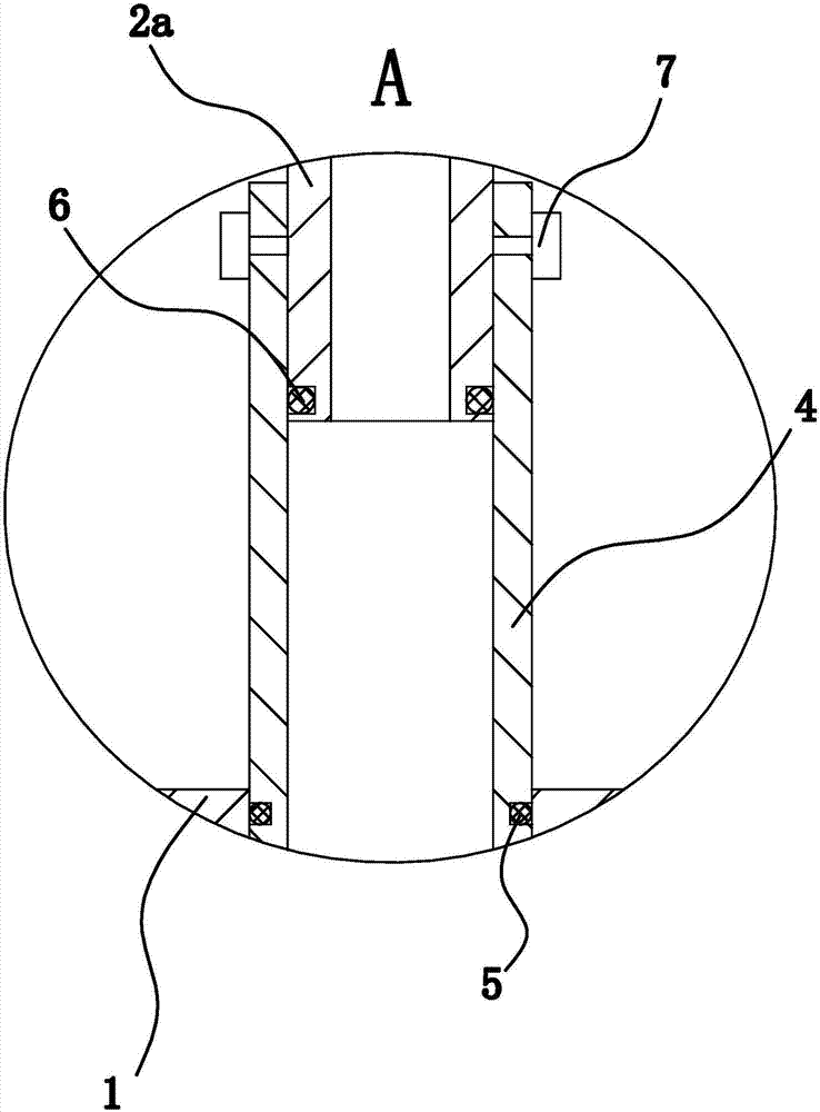
[0031] The structure and principle of this second embodiment are basically the same as that of the first embodiment, except that the outer wall of the drain pipe 4 has an annular shoulder, and the lower end surface of the annular shoulder is attached to and fixed with a ring-shaped rubber. Pad, and the lower end surface of the rubber pad abuts against the inner bottom wall of the cylinder body 1.

Embodiment 3

[0033] The structure and principle of the third embodiment are basically the same as those of the first embodiment, except that the detachable locking mechanism includes the threaded hole 2 penetrating through the side wall of the drain pipe 4 and the threaded hole provided on the side wall of the permeable part 2a Three and the bolt two screwed in the threaded hole two, there are several threaded holes three distributed along the axial direction of the water-permeable part 2a, and the end of the bolt two is screwed in one of the threaded holes three.


PUM


Abstract

The invention provides a combined fish tank, which belongs to the technical field of daily necessities. It solves the problem of poor practicability of the existing flower pots with fish tanks. The combined fish tank includes a tank body made of transparent glass and a flower pot vertically arranged in the tank body. The bottom of the flower pot has a cylindrically protruding water-permeable part. The filter screen of the upper cavity and the lower cavity, the upper cavity communicates with the inner cavity of the flower pot, the upper cavity and the lower cavity communicate through the mesh of the filter screen, the bottom of the cylinder body is vertically penetrated with drainage holes, and the drainage holes are vertically arranged There is a circular tube-shaped drain pipe, which is sealed and fixed with the cylinder body. The upper end of the drain pipe extends out of the drain hole, and the lower end of the permeable part is inserted into the drain pipe. There is an O-ring between the permeable part and the drain pipe to make the two connected and sealed. First, the permeable part can slide along the axial direction of the drain pipe, and a detachable locking mechanism that can limit the sliding of the permeable part is provided between the two. The combined fish tank has the advantage of high practicability.

Description

technical field [0001] The invention belongs to the technical field of daily necessities, and relates to a fish tank, in particular to a combined fish tank. Background technique [0002] In order to save the space taken by fish tanks and flower pots, there are many products combining fish tanks and flower pots on the market, and this product can reduce the space occupied by fish tanks and flower pots in the horizontal direction. [0003] For example, a flower pot with a fish tank disclosed in the Chinese patent library [application number: 201110194408.3; authorized announcement number: CN 102870616 A] includes a flower pot body, and a vent hole is provided at the bottom of the flower pot body. An outer body made of transparent material is provided, an annular fish tank device is formed between the flower pot body and the outer body, and a drain pipe is provided near the bottom of the outer body, and a drain pipe is provided on the drain pipe. There is a valve; the flower p...

Claims


Application Information

Patent Timeline
Patent Type & Authority Applications(China)
IPC IPC(8): A01K63/00A01K63/04A01G9/02
CPCA01K63/003A01G9/02
Inventor 凃柳芸
Owner 南京卓策知识产权服务有限公司
Why Eureka
Try Eureka