LED ring light source used for visual inspection lighting

A ring light source and visual inspection technology, which is applied to the components of lighting devices, cooling/heating devices of lighting devices, light sources, etc., can solve the problems of poor flexibility and low utilization rate, and achieve good contrast

Pending Publication Date: 2017-12-26
李劲松
View PDF0 Cites 5 Cited by
  • Summary
  • Abstract
  • Description
  • Claims
  • Application Information

AI Technical Summary

Problems solved by technology

Nowadays, in the image size measurement industry, the ring light source uses fixed angles for lighting, and cannot meet the needs of providing more delicate changes in lighting angles according to different products under test. Often, special light sources are designed for specific projects to achieve lighting, and the utilization rate is low. , poor flexibility and other disadvantages, cannot meet today's increasingly higher requirements for intelligence, efficiency and precision
[0003] In addition, the light sources on the market are often monochromatic light sources or a simple combination of RGB colors, and for some products with complex colors, it is often necessary to change the lighting of different color temperatures to better highlight the contrast of the characteristic part of the image.

Method used


Image

  • LED ring light source used for visual inspection lighting
  • LED ring light source used for visual inspection lighting
  • LED ring light source used for visual inspection lighting

Examples


Embodiment Construction

[0040] In order to make the objectives, technical solutions and advantages of the present invention clearer, the present invention will be further described in detail below with reference to the accompanying drawings.

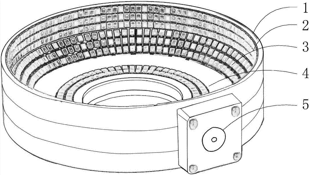
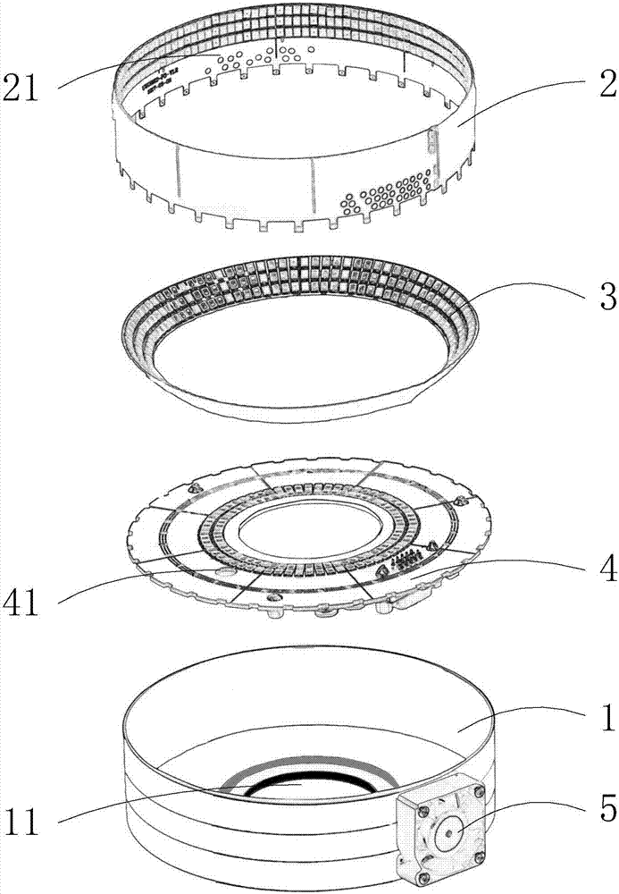
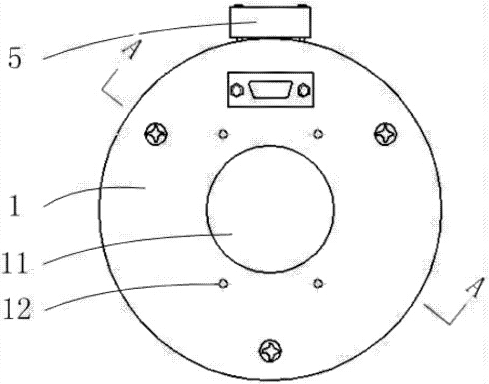
[0041] Such as Figure 1-6 As shown, the LED ring light source for visual inspection lighting disclosed in the present invention includes a housing 1, an outer ring light-emitting disk 2, a middle ring light-emitting disk 3, and an inner ring light-emitting disk 4. The housing 1 is a cylinder with an open top surface. , The bottom surface of the housing 1 is provided with a through hole 11; the inner ring light-emitting disk 4 is installed on the bottom surface of the housing 1; the lower edge of the outer ring light-emitting disk 2 is connected to the outer edge of the inner ring light-emitting disk 4; The ring light-emitting disk 2 is connected, the inner edge of the middle-ring light-emitting disk 3 is connected to the inner-ring light-emitting disk 4, and ther...


PUM


Abstract

The invention discloses an LED ring light source for visual detection and illumination, which belongs to the field of machine vision detection, and comprises a shell, an outer ring light disc, a middle ring light disc, and an inner ring light disc. The shell is a cylinder with an open top surface. The bottom surface of the shell is provided with a through hole; the inner ring luminous disc is installed on the bottom surface of the shell; the lower edge of the outer ring luminous disc is connected with the outer edge of the inner ring luminous disc; the outer edge of the middle ring luminous disc is connected with the outer ring The discs are connected, the inner edge of the middle ring luminous disc is connected with the inner ring luminous disc, and there is an included angle a between the middle ring luminous disc and the inner ring luminous disc. The present invention can provide flexible low-angle lighting effects with the free lifting of the lifting mechanism; the red, green, blue, and white four-color LEDs are arranged in a certain way, divided into 3 rings and 8 areas for control, and more flexible by adjusting different areas. Color LEDs are used for color mixing, while increasing the range of use of the light source.

Description

Technical field [0001] The invention relates to a machine vision ring light source, in particular to an LED ring light source for visual inspection lighting. Background technique [0002] The core of the machine vision system is image acquisition and processing. All information comes from the image, and the quality of the image itself is extremely critical to the entire visual system. The light source is an important factor to ensure the image quality of the image machine vision system, which directly affects the quality of the input data and at least 30% of the application effect. Nowadays in the image size measurement industry, the ring light source uses a fixed number of angles for lighting, and cannot meet the demand for more delicate changes in the lighting angle according to different products under test. It is often designed for specific projects to achieve lighting with special light sources, which has low utilization rate. , Poor flexibility and other drawbacks, can no...

Claims


Application Information

Patent Timeline
Patent Type & Authority Applications(China)
IPC IPC(8): F21S8/00F21V14/02F21V19/00F21V23/00F21V29/503F21V29/67F21V29/83F21Y103/33F21Y113/10F21Y115/10
CPCF21S8/00F21V14/02F21V19/001F21V23/003F21V29/503F21V29/67F21V29/83F21Y2103/33F21Y2113/10F21Y2115/10
Inventor 李劲松
Owner 李劲松
Why Eureka
Try Eureka