Cooling device for CPU (Central Processing Unit)

A heat dissipation device and heat dissipation chamber technology, applied in the direction of instruments, electrical digital data processing, digital data processing components, etc., can solve the problems of heat dissipation fan blades not being able to dissipate heat, heat evacuation, and ability not to be fully utilized, etc., to achieve faster The effect of heat evacuation speed and avoiding the influence of heat dissipation effect

Pending Publication Date: 2017-12-26
重庆市荣昌区索领网络科技有限公司
View PDF0 Cites 2 Cited by
  • Summary
  • Abstract
  • Description
  • Claims
  • Application Information

AI Technical Summary

Problems solved by technology

With the rapid development of the computer industry, the processing power of the computer is getting stronger and stronger, and the computing power of the CPU is also increasing day by day, and the resulting heat dissipation is also becoming more and more serious. If the heat in the computer is not evacuated quickly, it will seriously affect the performance of the computer. , its ability will not be fully utilized
The current CPU cooling device usually installs the heat dissipation blades on the upper end of the heat conduction sheet, and the heat on the heat conduction sheet is evacuated through the heat dissipation blades. Since the heat dissipation blades are arranged on the upper end of the heat conduction sheet, the heat dissipation blades cannot effectively dissipate heat for the CPU. , causing the heat to not be evacuated in time, which seriously affects the performance of the computer, and after the user uses it for a long time, dust is easy to accumulate on the cooling device, which affects the heat dissipation effect, and excessive dust accumulation on the circuit board will also seriously affect the performance of the computer. affect computer performance

Method used


Image

  • Cooling device for CPU (Central Processing Unit)
  • Cooling device for CPU (Central Processing Unit)

Examples


Embodiment Construction

[0013] The following will clearly and completely describe the technical solutions in the embodiments of the present invention with reference to the accompanying drawings in the embodiments of the present invention. Obviously, the described embodiments are only some, not all, embodiments of the present invention. Based on the embodiments of the present invention, all other embodiments obtained by persons of ordinary skill in the art without making creative efforts belong to the protection scope of the present invention.

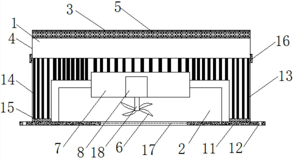
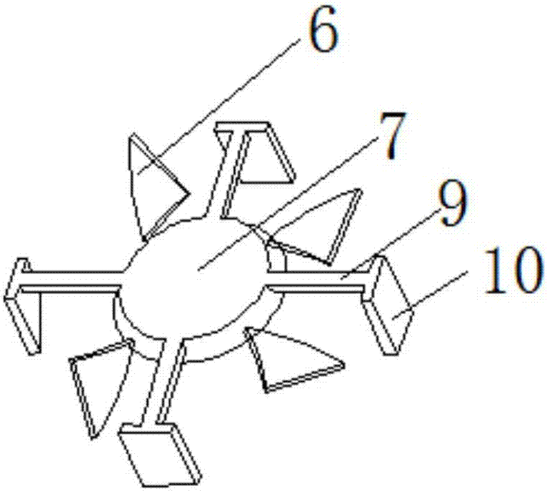
[0014] see Figure 1-2 , the present invention provides a technical solution: a cooling device for a CPU, including a dust removal chamber 1 and a heat dissipation chamber 2, the dust removal chamber 1 can effectively remove dust in the air, thereby avoiding the influence of dust on the heat dissipation effect and the computer performance , the dust removal chamber 1 includes a filter layer 3 and a connecting plate 4, the inside of the filter layer 3 is provid...


PUM


Abstract

The invention discloses a CPU heat dissipation device, which comprises a dust removal chamber and a heat dissipation chamber, the dust removal chamber includes a filter layer and a connecting plate, a filter screen is arranged inside the filter layer, and fan blades are arranged inside the heat dissipation chamber , the top of the fan blade is provided with a circular block, the interior of the circular block is provided with a motor, the motor is connected to the fan blade through a rotating shaft, and a bracket is provided on the circular block. The heat sink of the CPU is equipped with thermal silica gel at the bottom of the heat conduction sheet. The heat conduction silica gel can better transmit the heat of the CPU to the heat conduction sheet, so that the heat can be evacuated in time. It can dissipate the heat in time for the CPU, and the fan blades are arranged inside the heat conduction chamber, so that the air blown by the fan blades flows between the heat conduction fins, which greatly speeds up the heat evacuation speed of the heat conduction elements. Through the dust removal chamber, it can Effectively remove dust in the air.

Description

technical field [0001] The invention relates to the technical field of computer accessories, in particular to a cooling device for a CPU. Background technique [0002] Computer (computer), commonly known as computer, is an electronic computing machine used for high-speed computing. It can perform numerical calculations, logical calculations, and also has storage and memory functions. It is a modern intelligent electronic device that can run according to the program and process massive data automatically and at high speed. Composed of hardware systems and software systems, computers without any software installed are called bare metal. With the rapid development of the computer industry, the processing power of the computer is getting stronger and stronger, and the computing power of the CPU is also increasing day by day, and the resulting heat dissipation is also becoming more and more serious. If the heat in the computer is not evacuated quickly, it will seriously affect t...

Claims


Application Information

Patent Timeline
Patent Type & Authority Applications(China)
IPC IPC(8): G06F1/20
CPCG06F1/20G06F1/203
Inventor 肖洋
Owner 重庆市荣昌区索领网络科技有限公司
Why Eureka
Try Eureka