Optical fiber sensing geological disaster monitoring system

A technology for geological disasters and monitoring systems, applied in instruments, alarms, etc., can solve problems such as inconvenient signal transmission

Inactive Publication Date: 2017-08-25
ZHONGSHAN TOPWARE ELECTRONICS TECH
View PDF4 Cites 4 Cited by
  • Summary
  • Abstract
  • Description
  • Claims
  • Application Information

AI Technical Summary

Problems solved by technology

[0004] The manufacturer hopes to apply optical fiber sensing technology in the geological layer to detect geological disasters, and based on the influence of the environment, it is not convenient to use wired methods to transmit signals

Method used


Image

  • Optical fiber sensing geological disaster monitoring system
  • Optical fiber sensing geological disaster monitoring system

Examples


Embodiment Construction

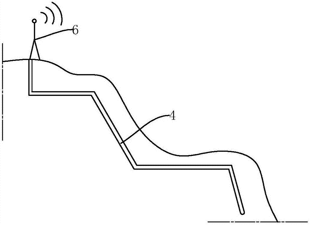
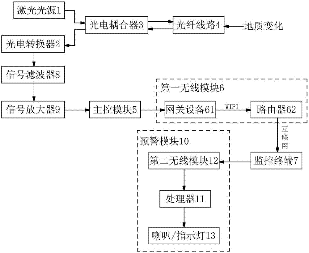
[0030] Such as figure 1 , figure 2 As shown, the optical fiber sensing geological disaster monitoring system of the present invention includes a laser light source 1 emitting optical signals, a photoelectric converter 2, an optical fiber coupler 3, an optical fiber line 4, a main control module 5, and a first wireless module 6; wherein, the main The control module 5 can be an MCU or a CPU, and the external monitoring terminal 7 can be a mobile device or a main control computer in a monitoring room. The optical fiber line 4 is a single-mode optical fiber line or a single-mode polarization-maintaining optical fiber line, and the optical fiber line 4 is buried horizontally In the geological layer and the distance between the optical fiber line 4 and the ground surface is greater than 2m, the optical fiber line 4 is soft and can be deformed according to terrain changes, so that the optical fiber line 4 can sense geological changes more accurately.

[0031] The optical fiber line...


PUM


Abstract

The invention discloses an optical fiber sensing geological disaster monitoring system, which includes a laser light source for emitting optical signals, a photoelectric converter, an optical fiber coupler, an optical fiber line, a main control module, and a first wireless module, and the optical fiber line is arranged on the geological layer to be detected In order to sense geological changes, the two ends of the fiber optic line are respectively connected to the other same side of the fiber coupler, one end of the same side of the fiber coupler is connected to the laser light source and the other end of the same side of the fiber coupler is connected to the photoelectric converter, the photoelectric The converter converts the optical signal into an electrical signal, and then inputs the geological change signal into the main control module. The first wireless module is electrically connected to the main control module so that the main control module and the external monitoring terminal form a wireless communication connection. This design The optical fiber line can be deeply immersed in the geological layer, and due to the softness of the optical fiber line, it can adapt to the terrain at will, accurately detect the geological change, and send it to the monitoring terminal in time through wireless communication.

Description

technical field [0001] The invention relates to a geological monitoring system, in particular to an optical fiber sensing geological disaster monitoring system. Background technique [0002] Traditionally, displacement sensors, humidity sensors, and acoustic wave sensors are mostly used for geological disaster detection, but these sensors have the problem of inaccurate signal measurement due to large external influences. [0003] Nowadays, the optical fiber sensing technology is becoming more and more perfect. The intensity, wavelength, frequency, phase, polarization state and other changes of the light to be measured are obtained after data demodulation. At the same time, the optical fiber sensing is sensitive, accurate, adaptable and compact. At the same time, it also has the performance of anti-electromagnetic and atomic radiation interference, the mechanical properties of thin diameter, soft quality and light weight, the electrical properties of insulation and non-induct...

Claims


Application Information

Patent Timeline
Patent Type & Authority Applications(China)
IPC IPC(8): G08B21/10G08B25/10
CPCG08B21/10G08B25/10
Inventor 陈钰龙周爱明王大波梁活强陈文伟冷小兵周柳奇
Owner ZHONGSHAN TOPWARE ELECTRONICS TECH
Why Eureka
Try Eureka