
Mixed-type permanent magnetic pole rotor

A permanent magnetic pole and mixed type technology, applied in the direction of magnetic circuit rotating parts, magnetic circuit, magnetic circuit shape/style/structure, etc., can solve the problems of easy demagnetization of magnetic steel and insufficient utilization of torque output magnetic steel, etc. Achieve the effect of reducing the weight of the rotor and increasing the torque density

Pending Publication Date: 2017-12-26
安徽栋霖电气有限公司
View PDF14 Cites 7 Cited by
  • Summary
  • Abstract
  • Description
  • Claims
  • Application Information

AI Technical Summary

Problems solved by technology

[0002] In existing permanent magnet synchronous motors, the radial magnetic field of the rotor magnets is "one", "V", "W" and so on. The disadvantage is that it can only form a unidirectional magnetic field, and the magnets per unit volume are not good in terms of torque output. to maximum utilization
[0003] For existing permanent magnet synchronous motors, the rotor magnets have "1" type or other forms of tangential magnetic field. The disadvantage of tangential magnetic field is that the magnetic steel is easy to demagnetize under the condition of high speed, weak magnetic field and high temperature.

Method used


Image

  • Mixed-type permanent magnetic pole rotor
  • Mixed-type permanent magnetic pole rotor
  • Mixed-type permanent magnetic pole rotor

Examples


Embodiment Construction

[0021] The present invention will be further described below in conjunction with the accompanying drawings and embodiments.

[0022] In order to understand the technical content of the present invention more clearly, the following examples are given in detail.

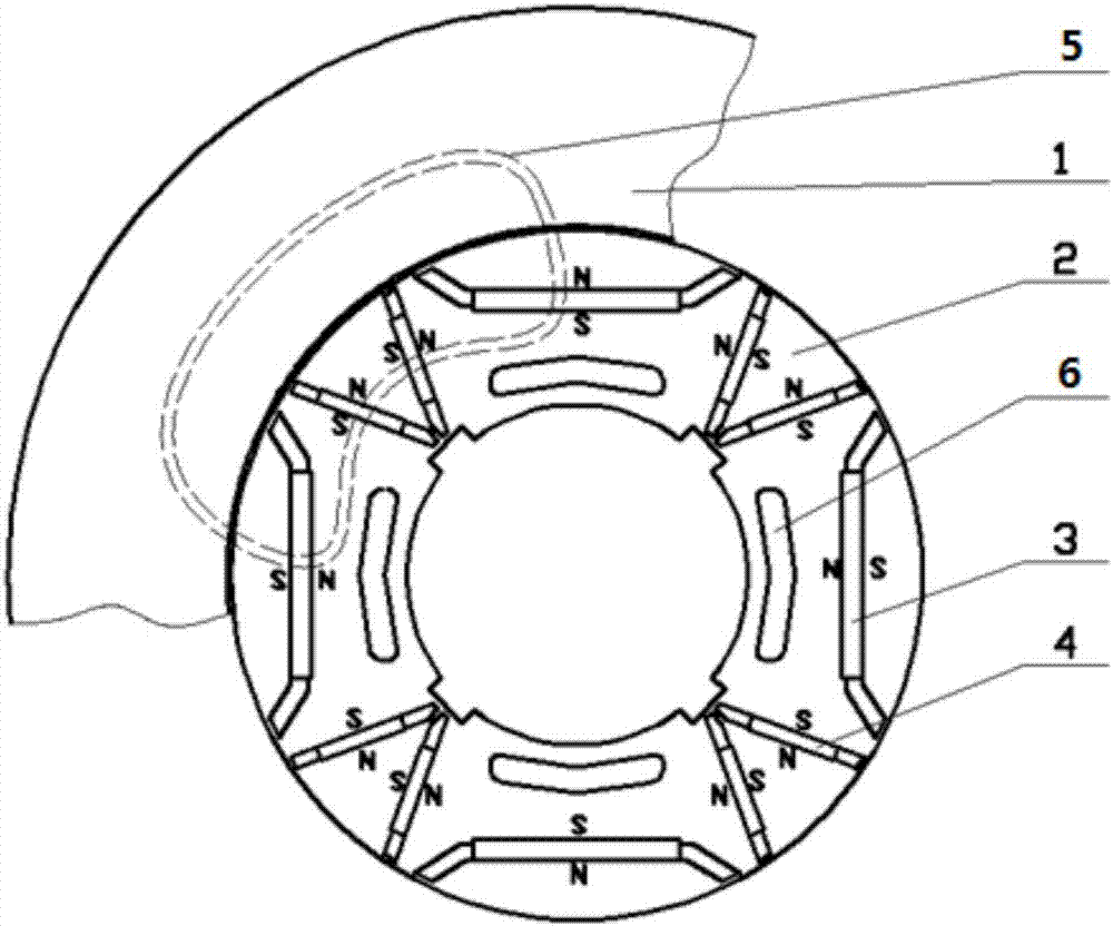
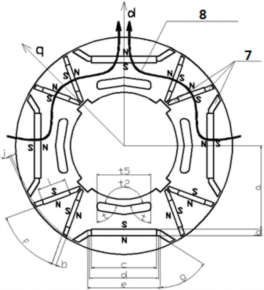
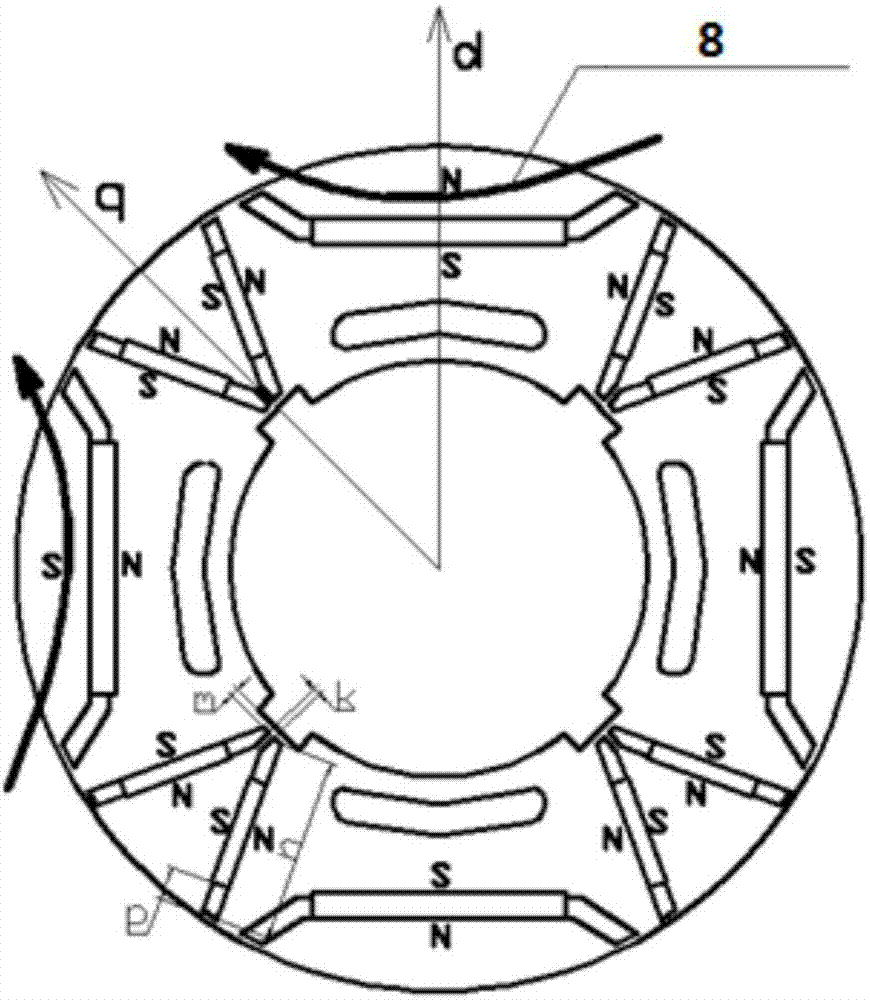
[0023] as attached figure 1 : The present invention provides a hybrid permanent magnet pole rotor structure, each pole magnetic steel is arranged in a shape such as a straight and V-shaped combination, "one" is 1 magnetic steel, which is a radial magnetic field, and "V" is 2 magnetic steels , is the tangential magnetic field. The N and S orientations of the magnets corresponding to the two adjacent poles are opposite. Between the "V" of the pole and the pole, a weight-reducing groove 6 of a certain size and shape is designed at an appropriate position.

[0024] This kind of rotor structure can be made into 4 poles, 6 poles, 8 poles... For the 4 pole rotor structure, twelve magnetic steel slots, twenty-four magnetic ...


PUM


Abstract

The invention discloses a mixed-type permanent magnetic pole rotor. The permanent magnetic pole rotor comprises a rotor core, n poles are arranged on the rotor core, each pole has three pieces of magnetic steel, the magnetic steel on each pole is arranged as the combination of a V shape and a horizontal stroke shape, the horizontal stroke shape stands for 1 piece of magnetic steel C and a radial magnetic field, the V shape stands for 2 pieces of magnetic steel D and a tangential magnetic field, and the N and S orientations of the magnetic steel corresponding to the adjacent poles are opposite. According to the mixed-type permanent magnetic pole rotor, the shortcomings of the rotor structure of the radial magnetic field of the magnetic steel and the rotor structure of the magnetic steel tangential field are combined, and the two rotor structure forms are applied simultaneously to the same type of motors, the shortcomings are complemented, and the external characteristics of the overall motor are improved.

Description

technical field [0001] The invention relates to a permanent magnet synchronous motor rotor required in the field of new energy vehicles or in the industrial field, in particular to a hybrid permanent magnet pole rotor. Background technique [0002] In existing permanent magnet synchronous motors, the radial magnetic field of the rotor magnets is "one", "V", "W" and so on. The disadvantage is that it can only form a unidirectional magnetic field, and the magnets per unit volume are not good in terms of torque output. to maximum utilization. [0003] In existing permanent magnet synchronous motors, the rotor magnetic steel has a "1" type or other forms of tangential magnetic field. The disadvantage of the tangential magnetic field is that the magnetic steel is easy to demagnetize under the condition of high-speed weak magnetic field and high temperature. Contents of the invention [0004] The purpose of the present invention is: to synthesize the shortcomings of the rotor s...

Claims


Application Information

Patent Timeline
Patent Type & Authority Applications(China)
IPC IPC(8): H02K1/27
CPCH02K1/2773
Inventor 李恕呼向东吴冬杨昆
Owner 安徽栋霖电气有限公司
Learn More