Heavy aluminum profile stretching straightener

A technology of stretching straightening machine and aluminum profile, which is applied in the field of metallurgical equipment, can solve the problems of heavy moving parts, impact of equipment and hydraulic system, large cross-sectional size of aluminum profile, etc., and achieve the effect of improving service life and avoiding impact

Inactive Publication Date: 2017-12-29
CHINA NAT HEAVY MACHINERY RES INSTCO
9 Cites 2 Cited by

AI-Extracted Technical Summary

Problems solved by technology

[0002] At present, domestic small and medium-sized aluminum profile offline stretching and straightening machines mostly adopt the center-loaded stretching method with no buffer and double cylinders inverted. When the material is broken, the impact energy is mainly absorbed by the main stretching cylinder; but for heavy-duty aluminum profiles Straight machine, due to the relatively large impact energy when the material is cut off,...

Method used

As shown in Figure 2, idle stroke buffer oil cylinder 8 is fixedly connected with stretching head 6, in order to buffering when the empty stroke of stretching head 6 moves fast and breaks material, its piston rod one end passes main stretching Oil cylinder 5 links to each other with frame 3, and the other end links to each other with frame positioning oil cylinder 7, to realize the precise positioning of frame 3.
Because frame 3 can move along stretching direction with respect to equipment foundation 9, frame 3 can move relative to foundation when breaki...

Abstract

The invention provides a heavy-duty aluminum profile stretching straightening machine, which comprises equipment foundation, main stretching oil cylinder, frame set on the equipment foundation, stretching head and tailstock, both of which are equipped with Jaws, the frame can slide relative to the equipment foundation along the stretching direction, the main stretching oil cylinder is set between the frame and the stretching head, the tail of the main stretching oil cylinder is against the front end of the frame, and the other end is against the front end of the frame. The stretching head and the tailstock are rigidly connected to the machine frame through the latch mechanism when stretching, and both the stretching head and the tailstock can move along the guide rails set on the foundation. The stretch leveler of this structure provided by the present invention can effectively absorb the impact energy when the material is broken, and can effectively avoid the impact on the main stretch oil cylinder and the equipment foundation, thereby improving the service life of the stretch leveler; The combined stretching oil cylinder enables the stretching head to move rapidly in empty space; the special jaw clamping form can ensure that the profile will not slip when stretched.

Technology Topic

Image

  • Heavy aluminum profile stretching straightener
  • Heavy aluminum profile stretching straightener

Examples

  • Experimental program(2)

Example Embodiment

[0018] Example 1:
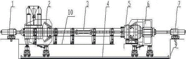
[0019] This embodiment provides a kind of heavy-duty aluminum extrusion straightening machine, comprising equipment foundation 9, main stretching oil cylinder 5, frame 3 located on equipment foundation 9, stretching head 6 and tailstock 2, stretching head 6 and the tailstock 2 are arranged at the two ends of the frame 3 respectively, the stretching head 6 and the tailstock 2 are provided with jaws, the frame 3 can move along the stretching direction relative to the equipment foundation 9, and the main pull Stretching oil cylinder 5 is located between frame 3 and stretching head 6, and the cylinder tail of this main stretching oil cylinder 5 is supported on frame 3 front ends, and the other end withstands stretching head 6, and described tailstock 2 and frame 3 rigidly connected, the stretching head 6 and the tailstock 2 are all slidably connected with the equipment foundation 9.
[0020] like figure 1 As shown, when the heavy-duty aluminum profile stretching straightener is stretched, the main stress components tailstock 22, frame 3, main stretching cylinder 5, stretching head 6 and the stretched profiles form a closed force-bearing For the frame, the stress centerlines of each stress member are in the same plane and symmetrical along the centerline, so no bending moment is generated during stretching, and the stretching force is not transmitted to the foundation.
[0021] Working process: When stretching the aluminum profile, after the tailstock 2 walks to the working position, insert the positioning pin into the positioning pin hole on the frame 3, the jaws on the stretching head 6 and the tailstock 2 clamp the aluminum profile, The main stretching cylinder 5 is connected with pressure oil to start stretching. After the aluminum profile is stretched in place, the main stretching cylinder 5 releases the pressure according to the set procedure to complete a stretching cycle;
[0022] In the event of material breakage, the tailstock 2 and the frame 3 are rigidly connected by positioning pins, the tailstock 2 drives the frame 3 to retreat quickly, and the frame 3 can move relative to the equipment foundation 9 without impacting the foundation; Stretching head 6 can advance rapidly after cutting off material, thereby frame 3 and stretching head 6 are separated from main stretching oil cylinder 5 when cutting off material, does not cause any impact to main stretching oil cylinder 5.
[0023] Since the frame 3 can move along the stretching direction relative to the equipment foundation 9, the frame 3 can move relative to the foundation when the material is cut off, without causing any impact on the foundation, and effectively avoiding damage to the equipment foundation 9 by the broken material; the main stretching cylinder 5 is arranged between the frame 3 and the stretching head 6, and the three are not fixed. When the material is cut off, the frame 3 and the stretching head 6 can be separated from the main stretching cylinder 5 without causing damage to the main stretching cylinder 5. Any impact, the main oil cylinder does not absorb any impact energy when the material is cut off, thus prolonging the service life of the main oil cylinder.

Example Embodiment

[0024] Example 2:
[0025] On the basis of Embodiment 1, this embodiment provides a heavy-duty aluminum extrusion straightening machine, the equipment foundation 9 is provided with a sliding support 10 and a guide rail 4, and the frame 3 is located on the sliding support 10, the stretching head 6 and the tailstock 2 are all provided with traveling wheels that cooperate with the guide rail 4.
[0026] The jaws are inclined pair of clamps, and the included angle with the horizontal direction is 20-25°. Ensure that the profile will not slip when stretched.
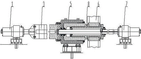
[0027] It also includes an idle stroke buffer oil cylinder 8, the main stretching oil cylinder 5 is a plunger cylinder, the tail of the empty stroke buffer oil cylinder 8 is fixedly connected with the stretching head 6, and one end of the piston rod passes through the main stretching oil cylinder 5 and the machine. Frame 3 is connected.
[0028] It also includes a buffer reset oil cylinder 1 and a frame positioning oil cylinder 7, the buffer reset oil cylinder 1 is connected to the tail of the frame 3, and the frame positioning oil cylinder 7 is connected to the cylinder body of the idle stroke buffer oil cylinder 8.
[0029] like figure 2 As shown, the idle stroke buffer cylinder 8 is fixedly connected with the stretching head 6, and is used for fast movement of the stretching head 6 and buffering when the material is cut off. One end of the piston rod passes through the main stretching cylinder 5 and the frame 3 Connected, and the other end is connected with frame positioning oil cylinder 7, to realize the precise positioning of frame 3.
[0030] Working process: When the heavy-duty aluminum profile stretching straightener is stretching the profile, after the tailstock 2 walks to the working position, insert the positioning pin into the positioning pin hole on the frame 3, and the stretching head 6 and the tailstock 2 Clamp the aluminum profile with the pair of clip-on pliers, press oil through the piston cavity of buffer reset oil cylinder 1 and idle stroke buffer oil cylinder 8, and pass pressure oil through main stretching oil cylinder 5 to start stretching. Under normal pulling conditions, after the profile is stretched in place, the main stretching oil cylinder 5, buffer reset oil cylinder 1, and idle stroke buffer oil cylinder 8 all release pressure according to the set program to complete a stretching cycle.
[0031] In the event of material breakage, the tailstock 2 and the frame 3 are rigidly connected by positioning pins, the tailstock 2 drives the frame 3 to retreat quickly, and the frame 3 can move relative to the equipment foundation 9 without impacting the foundation; Stretching head 6 can advance rapidly after cutting off material, thereby frame 3 and stretching head 6 are separated from main stretching oil cylinder 5 when cutting off material, does not cause any impact to main stretching oil cylinder 5. At the same time, the buffer reset oil cylinder 1 at the tail of the frame 3 will buffer the frame 3 in time to absorb the impact energy of the material breaking; the stretching head 6 will move forward rapidly after the material is cut off, and at this time, the empty stroke moving buffer oil cylinder will promptly move the stretching head 6. Buffer to absorb the impact energy of material breaking.

PUM

no PUM

Description & Claims & Application Information

We can also present the details of the Description, Claims and Application information to help users get a comprehensive understanding of the technical details of the patent, such as background art, summary of invention, brief description of drawings, description of embodiments, and other original content. On the other hand, users can also determine the specific scope of protection of the technology through the list of claims; as well as understand the changes in the life cycle of the technology with the presentation of the patent timeline. Login to view more.

Similar technology patents

Vehicle-mounted battery installation platform

InactiveCN104723304AAvoid shockRealize the adjustment of spatial postureWork benchesButt jointLinkage concept
Owner:王昕

Classification and recommendation of technical efficacy words

  • Avoid shock
  • Extended service life
Why Eureka
Try Eureka