Straight-grain shaft machining equipment
A kind of processing equipment and straight grain technology, applied in the field of straight grain shaft processing equipment, can solve the problems of low processing efficiency, error, and uneven distribution of ruled lines, etc., to improve processing accuracy and efficiency, and simplify the driving structure , Machining accuracy and efficiency improvement effect
- Summary
- Abstract
- Description
- Claims
- Application Information
AI Technical Summary
Problems solved by technology
Method used
Image

Examples
Embodiment Construction
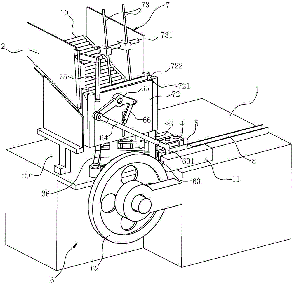
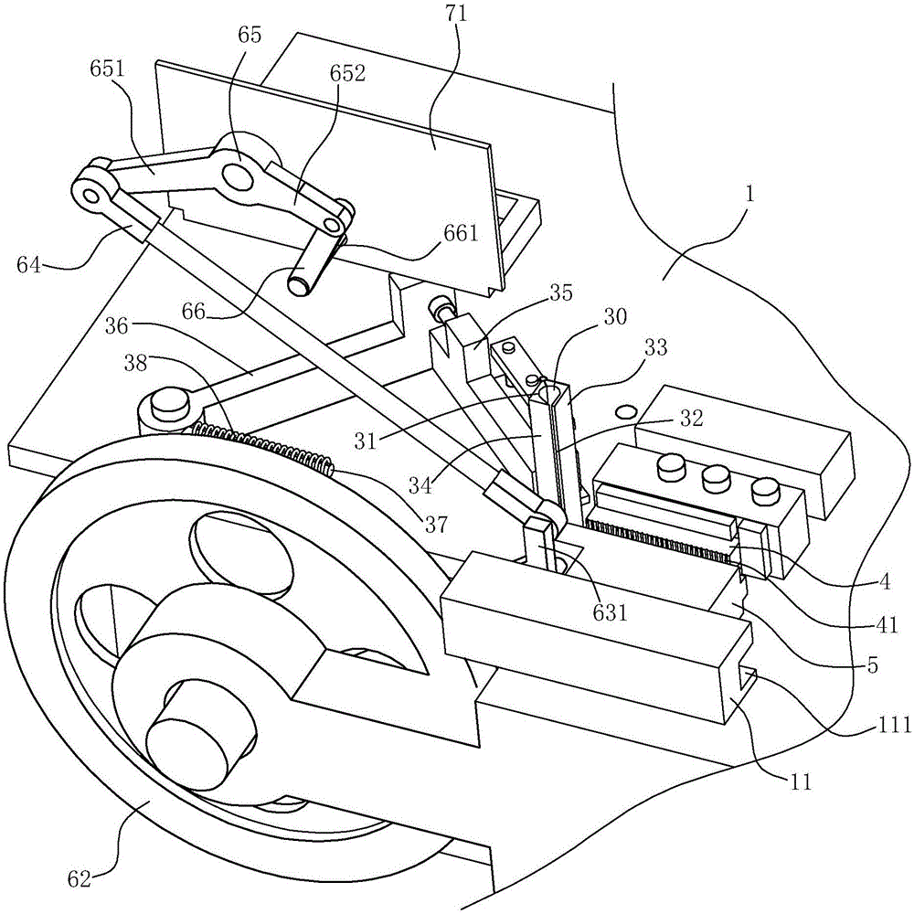
[0028] The present invention will be further described in detail below in conjunction with the accompanying drawings and embodiments.
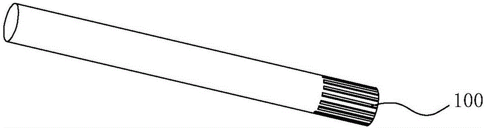
[0029] Such as Figure 2-6As shown, the processing equipment of the ruled shaft in this embodiment includes a base 1, a storage box 2, a temporary storage bin 3, a first processing rack 4, a second processing rack 5, a driving mechanism 6, and a feeding mechanism 7 And discharging mechanism 8. The base 1 of this embodiment is used to install other components, and the bottom sides of the material storage box 2 are respectively provided with downwardly extending legs 29, and the material storage box 2 is mounted on the base 1 through the legs 29, and the temporary storage bin 3 is set on the base 1 and is located below the storage box 2. The top of the temporary storage 3 is provided with an input port 31 through which the shaft 10 to be processed is vertically entered. The side of the temporary storage 3 is provided with an output that can be ...
PUM
 Abstract
Description
Claims
Application Information