
Automatic feeding mechanism of boring tool

An automatic feeding and boring tool technology, which is applied to metal processing machinery parts, metal processing equipment, feeding devices, etc., can solve the problems of low processing efficiency and few feeding directions

Pending Publication Date: 2017-12-29
JINGYIHENGZHUN TIANJIN CNC EQUIP CO LTD
View PDF0 Cites 4 Cited by
  • Summary
  • Abstract
  • Description
  • Claims
  • Application Information

AI Technical Summary

Problems solved by technology

The boring tool can be used on boring machines, lathes or milling machines. The existing boring tool feeding mechanism has simple structure and few feeding directions. When cutting chips of complex parts, it is necessary to constantly adjust the position of the parts, and the processing efficiency is low. Therefore, we propose an automatic feeding mechanism for boring cutter

Method used


Image

  • Automatic feeding mechanism of boring tool
  • Automatic feeding mechanism of boring tool
  • Automatic feeding mechanism of boring tool

Examples


Embodiment

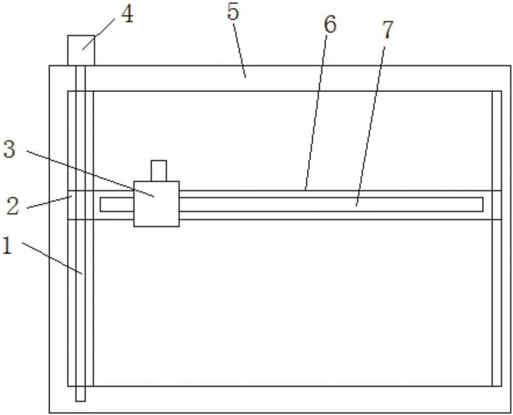
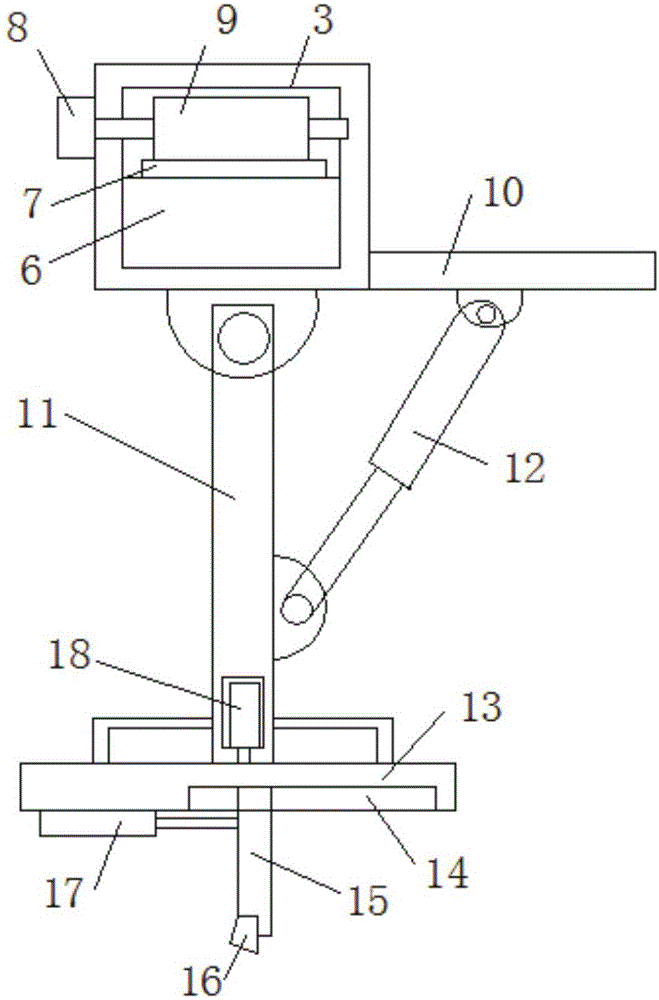
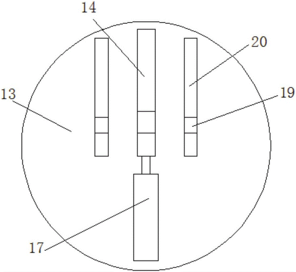
[0018] Embodiment: When in use, the fixed frame 5 is fixed on the machine tool through the fixed plate and screws, the first motor 4 drives the threaded rod 1 to rotate, the threaded rod 1 is threadedly connected with the slide block 2, and drives the cross bar 6 to move back and forth, and the second The motor 8 drives the gear 9 to rotate, the gear 9 and the rack 7 mesh with each other, and drives the movable frame 3 to move left and right on the cross bar 6. The third motor 18 drives the rotating plate 13 to rotate, and the rotating plate 13 drives the cutter head 16 to rotate for cutting and drilling. When reaming is required, the push rod motor 17 drives the connecting rod 15 in the movable groove 14 Inner movement makes the cutter head 16 continuously deviate from the circle to ream the hole. At the same time, the connecting rod 15 drives the limit rod 19 to slide in the limit groove 20, so that the cutter head 16 is more stable. The device can realize left and right forw...


PUM


Abstract

The invention discloses an automatic feeding mechanism of a boring tool. The mechanism comprises a fixed frame; a cross bar is slidingly connected into the fixed frame; slide blocks are respectively arranged at the two ends of the cross bar; chutes are respectively formed in two side inner walls of the fixed frame; the slide blocks are slidingly connected into the chutes; a first motor is fixed on one side outer wall of the fixed frame through screws; an output shaft of the first motor is connected with a thread rod; the thread rod is rotationally connected into one chute; the thread rod is in threaded connection with the slide blocks in the chutes; a rack is mounted on the top end side wall of the cross bar; a movable frame sleeves the cross bar; a second motor is fixed on one side wall of the movable frame through screws; an output shaft of the second motor is connected with a gear; and the gear is positioned in the movable frame. The mechanism can realize movement in all directions, can realize adjustment of the machining angle, brings convenience to machining of round holes or arcs with different sizes, has no need to repeatedly adjust the positions of objects to be machined, and is high in machining efficiency.

Description

technical field [0001] The invention relates to the technical field of lathe processing, in particular to an automatic feeding mechanism for a boring tool. Background technique [0002] Boring tool is a kind of hole processing tool, generally with round handle, and there are also larger workpieces with square tool holders, which are generally found in vertical lathes. The most commonly used occasions are inner hole processing, hole reaming, profiling, etc. But not only the inner hole can be processed, the outer circle of the end face can also be processed, but it is not used in this way. The boring tool is a kind of boring tool, usually with a round handle, and there are also large workpieces that use square tool holders. Commonly used occasions are inner hole processing, reaming, profiling, etc. A tool with one or two cutting sections designed to rough, semi-finish, or finish an existing hole. The boring tool can be used on boring machines, lathes or milling machines. The...

Claims


Application Information

Patent Timeline
IPC IPC(8): B23Q5/28
CPCB23Q5/28
Inventor 王振飞
Owner JINGYIHENGZHUN TIANJIN CNC EQUIP CO LTD
Learn More