
Method for fixing, hoisting and carrying hydraulic support pushing rod

A technology of hydraulic support and push rod, which is applied in the directions of pillar/support, earthwork drilling, transportation and packaging, etc., can solve the problem of high hanging distance between the support base and the trolley, difficulty in loading and fixing the hydraulic support, equipment damage to personal accidents, etc. problems, to achieve the effect of reducing the lifting height and the difficulty of lifting, increasing the guarantee of safe production, and solving the difficulty of loading.

Inactive Publication Date: 2017-12-29
山西华阳集团新能股份有限公司
View PDF6 Cites 0 Cited by
  • Summary
  • Abstract
  • Description
  • Claims
  • Application Information

AI Technical Summary

Problems solved by technology

During the downhole transportation, because the push rod of the support and the base form a V shape, the distance between the support base and the trolley is relatively high, it is difficult to load and fix the hydraulic support, and it also causes problems such as long loading and unloading time
Workers work under the bracket with a high lifting height for a long time, which also has a relatively large safety hazard. If the crane fails or the wire rope breaks, it will produce a large impact, causing equipment damage and personal accidental injury and other accidents.

Method used


Image

  • Method for fixing, hoisting and carrying hydraulic support pushing rod

Examples


Embodiment Construction

[0015] The hydraulic support push rod of the present invention is fixed lifting and carrying method is:

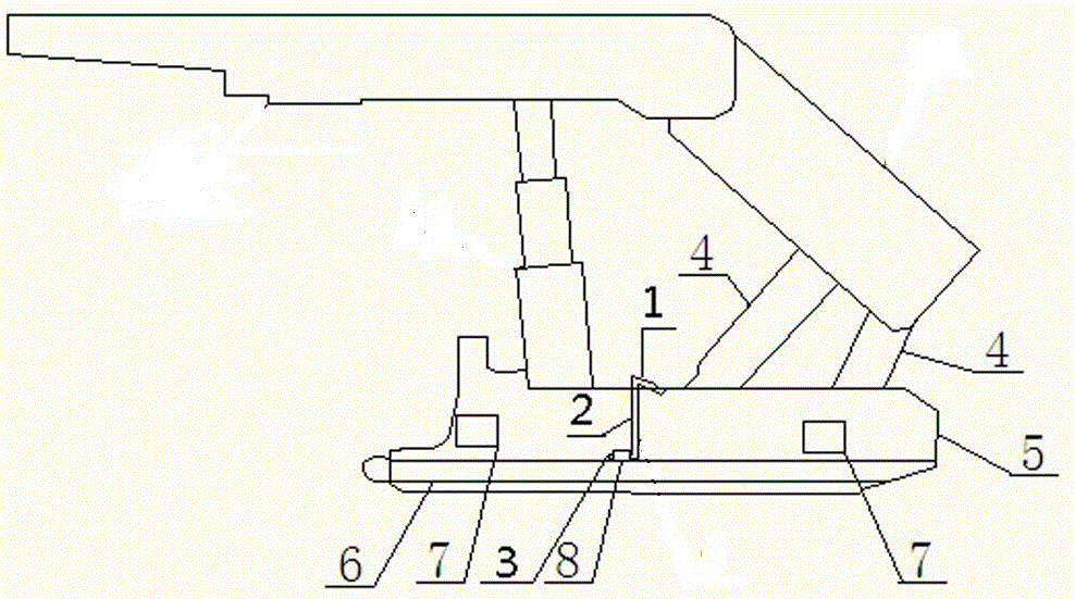
[0016] (1) Lifting and transporting a hydraulic support requires a set of special hook devices, and a set of special hook devices includes two fixing rings 8 and two special fixing hooks. There are two right-angle bends on the special fixed hook. The fixed hook includes upper flat hook 1, vertical bar 2 and lower flat hook 3; between upper flat hook 1 and middle vertical bar 2, between middle vertical bar 2 and lower flat hook 3, The included angle between the upper flat hook 1 and the lower flat hook 3 is a vertical angle of 90 degrees; the upper flat hook 1 is longer than the lower flat hook 3; the fixing ring 2 is a steel pipe that can be inserted into the lower flat hook 3 of the fixing hook;

[0017] (2) Weld two fixing rings 8 to the center points on the left and right sides of the top surface of the hydraulic support push rod 6, at a distance of 1400mm from the fron...


PUM


Abstract

The invention provides a method for fixing, hoisting and carrying a hydraulic support pushing rod, and aims at avoiding the hoisting difficulty caused by hanging down of the middle of the pushing rod. The method is characterized in that a special hanging hook device is independently manufactured, wherein the special hanging hook device comprises two fixing hanging hooks and two fixing rings; each fixing hanging hook comprises an upper horizontal hook, a vertical rod and a lower horizontal hook; the included angle between each upper horizontal hook and the corresponding intermediate vertical rod, the included angle between each intermediate vertical road and the corresponding lower horizontal hook, and the included angle between each upper horizontal hook and the corresponding lower horizontal hook are 90 degrees; the fixing rings are steel pipes and are welded in the center of the top surface of the hydraulic support pushing rod; the upper horizontal hooks of the two fixing hanging hooks are correspondingly clamped to the upper top surfaces of a left hydraulic support base and a right hydraulic support base; the two lower horizontal hooks are correspondingly inserted into two fixing rings on the top surface of the pushing rod, so that the pushing rod and the support bases are fixedly connected as a whole; the hoisting hooks are mounted on hoisting loading and unloading holes in the hydraulic support bases; then a steel wire rope is connected and stretched by a crane for hoisting; the hydraulic support parallelly moves onto a loading handcart or is hoisted onto an automobile for transporting.

Description

technical field [0001] The invention relates to a lifting and conveying method for fixing a push rod of a hydraulic support. Background technique [0002] At present, during the lifting process of the hydraulic support, the push rod cannot be in a straight line because the connection is fixed by a pin shaft, and the knuckle is V-shaped, and the lifting height is more than 1.5 meters higher than the support base to move the support. During the downhole transportation, because the push rod of the support and the base form a V shape, the suspension distance between the support base and the trolley is relatively high, it is difficult to load and fix the hydraulic support, and it also causes problems such as long loading and unloading time. Workers work under the support with high lifting height for a long time, which also has relatively large safety hazards. If the crane fails or the wire rope breaks, it will produce a large impact, resulting in equipment damage and personal acc...

Claims


Application Information

Patent Timeline
Patent Type & Authority Applications(China)
IPC IPC(8): B66C13/04B66C1/10E21D15/00E21D15/58
CPCB66C1/10B66C13/04E21D15/002E21D15/58
Inventor 温文文刘晓鹏李潇伟李国栋李旭钢张同国
Owner 山西华阳集团新能股份有限公司
Learn More