
Steam generator device and clothing drying machine

A technology for steam generators and clothes dryers, applied in steam generation, steam generation methods, household clothes dryers, etc., which can solve problems such as steam leakage, leakage, and easy failure, and achieve the effect of ensuring sealing and improving safety performance

Inactive Publication Date: 2017-12-29
WUXI LITTLE SWAN ELECTRIC CO LTD
View PDF5 Cites 1 Cited by
  • Summary
  • Abstract
  • Description
  • Claims
  • Application Information

AI Technical Summary

Problems solved by technology

[0003] In related technologies, the sealing structure of the steam generator device generally adopts labyrinth seal, groove seal, etc., and this sealing structure is generally only suitable for normal temperature environment. In high pressure environment, it is easy to fail and cause leakage; traditional sealing methods also have increased flexibility. Materials such as rubber rings, etc., are sealed by pressing them tightly, and some are sealed by filling glue. The method of adding elastic materials can only ensure the sealing at room temperature. When the steam generator is working, the temperature rises. The material expands with heat and contracts with cold, and the generator expands due to high temperature. It is difficult to ensure continuous sealing at the joint with the rubber ring. In addition, the high-pressure environment can easily cause the seal to fail and steam to leak; and the sealing method of glue filling, the glue is in the It is easy to fail in a high temperature environment, causing steam to leak
Therefore, the structural sealing method is more reliable in the high-temperature, high-humidity, and high-pressure working environment of the steam generator heating device, and the sealing structure of the labyrinth seal and the groove seal cannot be simply used.

Method used


Image

  • Steam generator device and clothing drying machine
  • Steam generator device and clothing drying machine
  • Steam generator device and clothing drying machine

Examples


Embodiment Construction

[0051] In order to understand the above-mentioned purpose, features and advantages of the present invention more clearly, the present invention will be further described in detail below in conjunction with the accompanying drawings and specific embodiments. It should be noted that, in the case of no conflict, the embodiments of the present application and the features in the embodiments can be combined with each other.

[0052] In the following description, many specific details are set forth in order to fully understand the present invention. However, the present invention can also be implemented in other ways than described here. Therefore, the protection scope of the present invention is not limited by the specific implementation disclosed below. Example limitations.

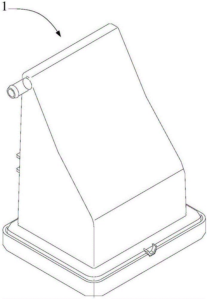
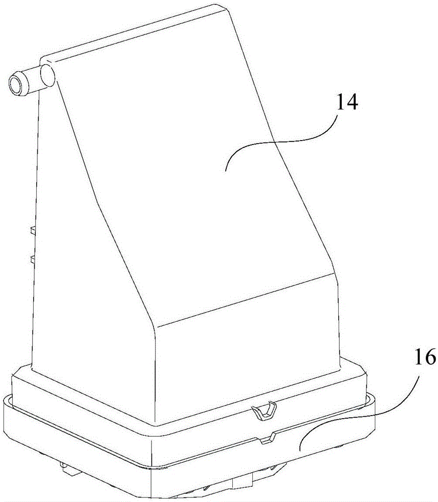
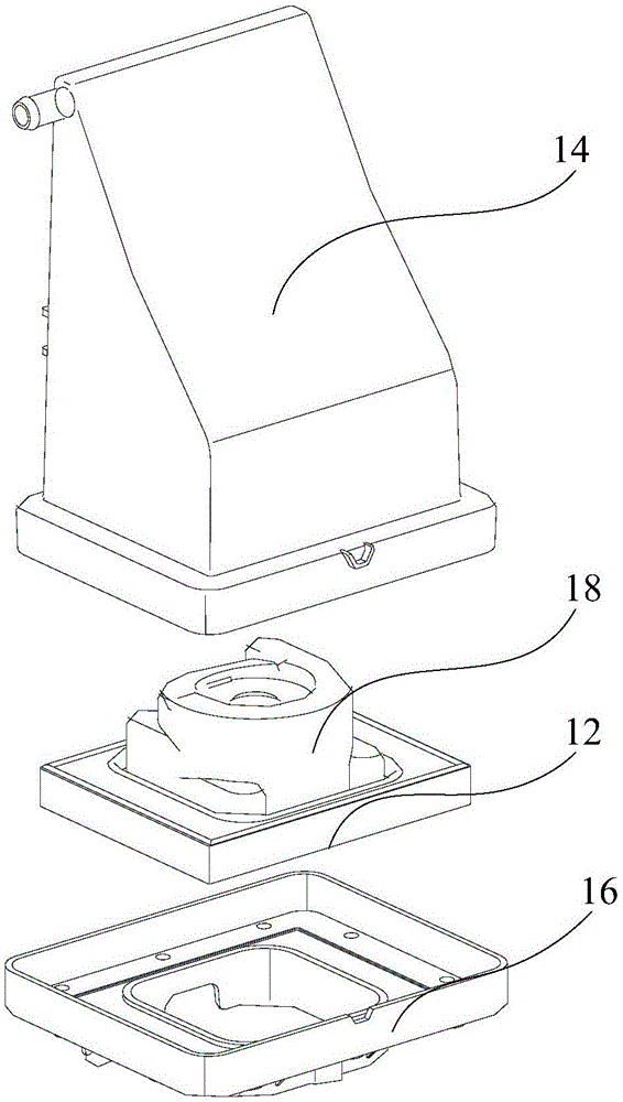
[0053] Refer below Figure 1 to Figure 14 The steam generator device 1 and clothes dryer provided according to some embodiments of the present invention will be described.

[0054] Such as Figure 1 to Fig...


PUM


Abstract

The invention provides a steam generator device and a clothing drying machine. The steam generator device is used for the clothing drying machine and comprises a steam generator container, a lower hold part, a heating block and a sealing structure, and the steam generator container is of a hollow cavity structure with the two open ends. The lower hold part is matched with an opening of one end of the steam generator container and connected with the steam generator container to form a mounting cavity. The heating block is arranged in the mounting cavity formed by the steam generator container and the lower hold part. The sealing structure is arranged on the connecting position of the steam generator container and the lower hold part and used for the sealing the connecting position of the steam generator container and the lower hold part. The steam device comprises the steam generator container, the lower hold part, the heating block and the sealing structure, sealing is ensured through the sealing structure, all parts are mutually matched, and thus water located in the mounting cavity is atomized into high-temperature high-pressure steam to be sprayed out, so that the effect on clothing ironing is achieved.

Description

technical field [0001] The present invention relates to the field of household electrical appliances, more specifically, to a steam generator device and a clothes dryer. Background technique [0002] At present, high-end clothes dryers also have the function of ironing clothes while drying clothes. Steam generators generally appear in this kind of clothes dryers, which heat water into steam to iron clothes. Therefore, steam The heater heating device is a harsh working environment of high temperature, high humidity and high pressure. [0003] In related technologies, the sealing structure of the steam generator device generally adopts labyrinth seal, groove seal, etc., and this sealing structure is generally only suitable for normal temperature environment. In high pressure environment, it is easy to fail and cause leakage; traditional sealing methods also have increased flexibility. Materials such as rubber rings, etc., are sealed by pressing them tightly, and some are seal...

Claims


Application Information

Patent Timeline
Patent Type & Authority Applications(China)
IPC IPC(8): F22B37/00F22B1/28D06F58/20F16J15/02
CPCF22B37/00D06F58/20F16J15/02F22B1/28
Inventor 徐玉高王浩吴祥忠谢邦明孙海峰
Owner WUXI LITTLE SWAN ELECTRIC CO LTD
Learn More