
Dual-frequency antenna of wireless communication equipment

A technology for wireless communication equipment and dual-frequency antennas, applied in mechanical equipment, electrical equipment structural parts, antenna supports/installation devices, etc., can solve the problems of heat accumulation, equipment damage, insufficient protection effect, etc., to improve the safety of use , Improve the protective effect and facilitate the discharge effect

Pending Publication Date: 2021-06-18
张家港艾富精密机电技术有限公司
View PDF0 Cites 0 Cited by
  • Summary
  • Abstract
  • Description
  • Claims
  • Application Information

AI Technical Summary

Problems solved by technology

[0005] The purpose of the present invention is to provide a dual-frequency antenna for wireless communication equipment, to solve the problem that the existing dual-frequency antenna for wireless communication equipment in the above-mentioned background technology is easy to damage the equipment due to its insufficient protection effect when in use, and further The service life of the dual-frequency antenna of the wireless communication device is reduced, and the self-radiation performance of the dual-frequency antenna of the existing wireless communication device is insufficient, which makes it easy to accumulate heat inside, and the dual-frequency antenna itself of the existing wireless communication device does not It has anti-seismic function, which further reduces the safety of the dual-frequency antenna of wireless communication equipment

Method used


Image

  • Dual-frequency antenna of wireless communication equipment
  • Dual-frequency antenna of wireless communication equipment
  • Dual-frequency antenna of wireless communication equipment

Examples


Embodiment Construction

[0027] The following will clearly and completely describe the technical solutions in the embodiments of the present invention with reference to the drawings in the embodiments of the present invention.

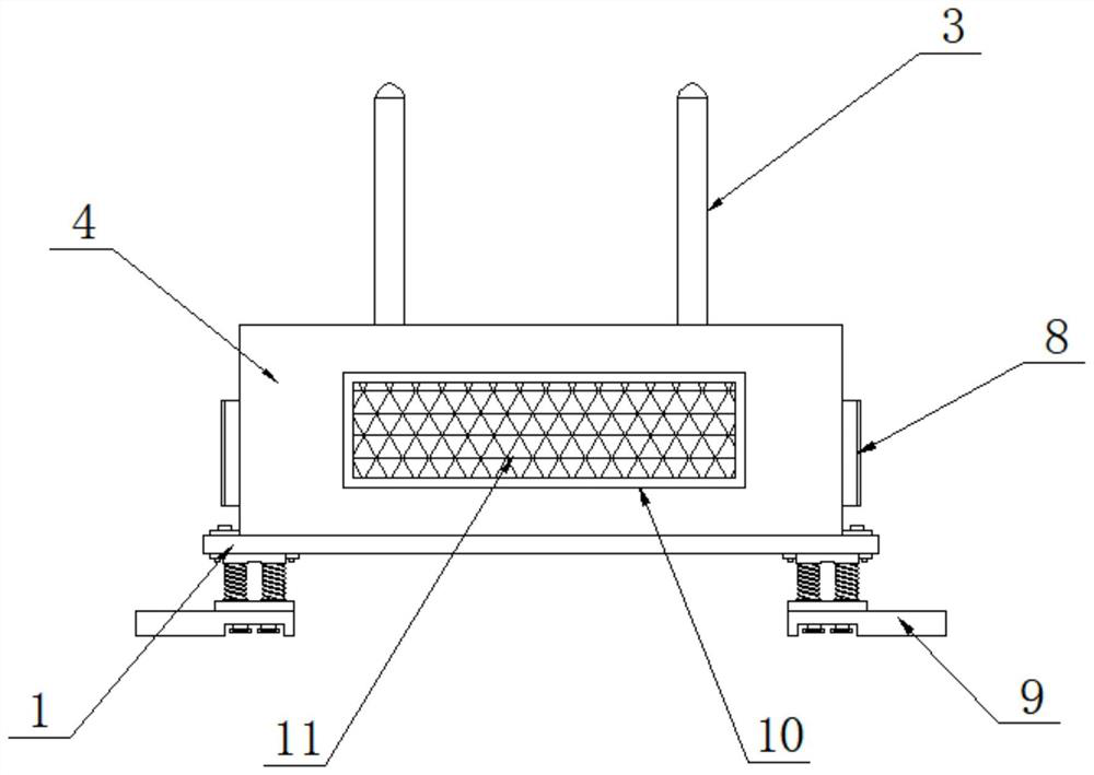
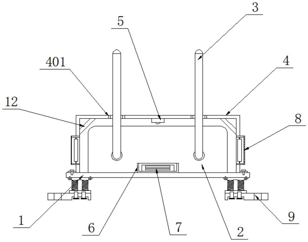
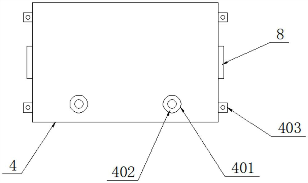
[0028] Such as Figure 1-6 As shown, the present invention provides a technical solution: a dual-frequency antenna for wireless communication equipment, including a supporting plate 1, a communication equipment main body 2 and a dual-frequency FRP antenna 3, and the communication equipment main body is installed in the middle of the top surface of the supporting plate 1 2. A dual-frequency FRP antenna 3 is installed on both sides of the surface of the main body 2 of the communication device, a protective cover 4 is provided on one side of the top surface of the supporting plate 1, and a temperature sensor 5 is installed in the middle of the top surface of the inner cavity of the protective cover 4 A storage box 6 is installed on one side of the main body 2 of the communication...


PUM


Abstract

A dual-frequency antenna of wireless communication equipment, disclosed in the invention, comprises a supporting plate, a communication equipment body and dual-frequency glass fiber reinforced plastic antennas, the communication equipment body is installed in the middle of the surface of the top of the supporting plate, the dual-frequency glass fiber reinforced plastic antennas are installed on the two sides of the surface of the communication equipment body, and a protective cover is arranged on one side of the surface of the top of the supporting plate. A temperature sensor is installed in the middle of the surface of the top of an inner cavity of the protective cover, a storage box is installed on one side of the communication equipment body, and a microcontroller is installed in an inner cavity of the storage box. The communication equipment body on the supporting plate can be protected through the protective cover, so the use safety of the communication equipment body is improved; and the temperature sensor and the microcontroller can monitor the internal temperature of the protective cover and can flexibly control the operation of a heat dissipation mechanism, so that the heat dissipation effect on the communication equipment body can be achieved, and the influence of external vibration on the communication equipment body on the supporting plate can be reduced through a supporting mechanism.

Description

technical field [0001] The invention relates to the technical field of wireless communication equipment, in particular to a dual-frequency antenna for wireless communication equipment. Background technique [0002] The English abbreviation is ICD, and the full name is Industrial Communication Device. This column will comprehensively introduce wired communication equipment and wireless communication equipment suitable for industrial control environments. Wired communication equipment mainly introduces solutions for serial communication on industrial sites, professional bus communication, industrial Ethernet communication and conversion equipment between various communication protocols. Wireless communication equipment is mainly wireless AP, wireless bridge, wireless network card, wireless lightning arrester, antenna and other equipment. [0003] However, existing dual-band antennas for wireless communication devices have the following disadvantages: [0004] When the dual-...

Claims


Application Information

Patent Timeline
IPC IPC(8): H01Q1/24H01Q1/42H05K7/20H05K5/02F16F15/067
CPCF16F15/067H01Q1/24H01Q1/42H05K5/0234H05K7/20136
Inventor 宫亮宫明
Owner 张家港艾富精密机电技术有限公司
Learn More