
Power transmission line bolt temperature measuring device and use method thereof

A technology for temperature measuring devices and transmission lines, applied in measuring devices, cable suspension devices, cable installation, etc., can solve the problems of reducing the shunting work efficiency of high-voltage electric lines, failing to clamp and detect bolts, and bolt detachment, etc. Achieve the effect of improving the safety of operation, facilitating maintenance and replacement, and avoiding detachment

Pending Publication Date: 2022-07-29
STATE GRID PUTIAN ELECTRIC POWER SUPPLY +2
View PDF0 Cites 0 Cited by
  • Summary
  • Abstract
  • Description
  • Claims
  • Application Information

AI Technical Summary

Problems solved by technology

[0004] The purpose of the present invention is to provide a transmission line bolt temperature measuring device and its use method, aiming at solving the problem of using high-voltage punctures for shunting in the prior art when shunting high-voltage electric lines. The piezoelectric circuit needs to be fixed with bolts when installing. Common punctures cannot clamp the bolts and detect their temperature, resulting in excessive temperature of the bolts due to high-voltage wires, causing damage to the bolts, etc., resulting in bolts from The punctured surface is detached, which reduces the work efficiency of the shunting of high-voltage electric lines

Method used


Image

  • Power transmission line bolt temperature measuring device and use method thereof
  • Power transmission line bolt temperature measuring device and use method thereof
  • Power transmission line bolt temperature measuring device and use method thereof

Examples


Embodiment 1

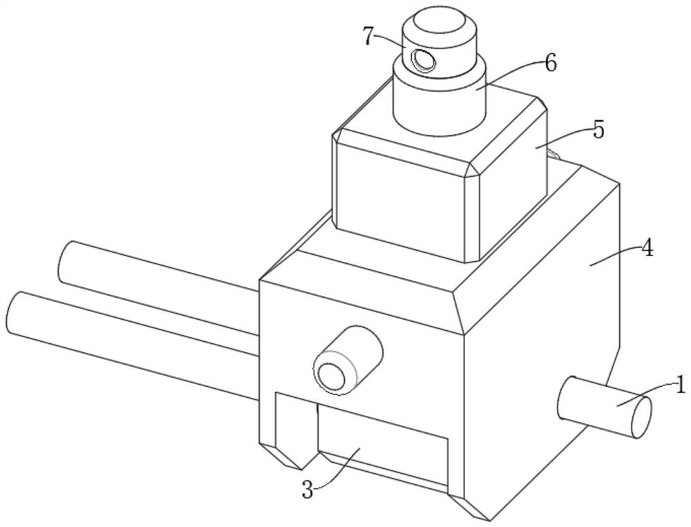
[0043] see figure 1 , the present invention provides the following technical solutions:

[0044] A transmission line bolt temperature measuring device and a method for using the same, comprising:

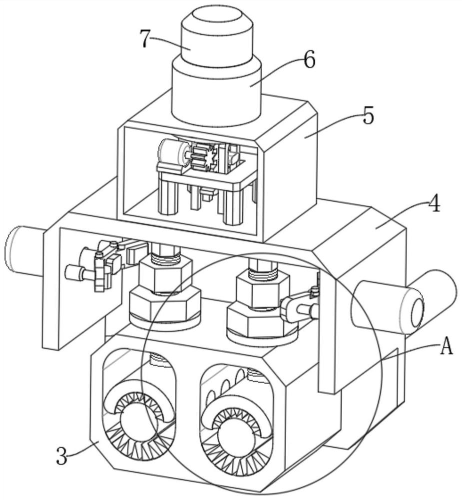
[0045] mounting shell 3;

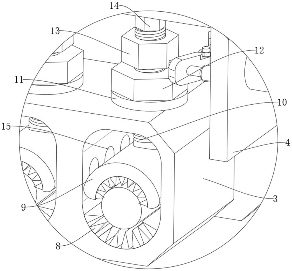
[0046] Two high-voltage transmission lines 1, both of which are slidably connected to the inner surface of the installation shell 3, the upper inner wall of the installation shell 3 is slidably connected with two threaded rods 10, and the circumferential surfaces of the two threaded rods 10 are all threadedly connected There is a second bolt 13;

[0047] protective shell 4, the protective shell 4 is slidably connected to the circumferential surfaces of the two high-voltage transmission lines 1, the upper end of the protective shell 4 is fixedly connected to the limiting shell 5, and the upper side of the limiting shell 5 is provided with an infrared thermometer 7;

[0048] Two sets of fixing mechanisms, both of which are arranged in the installation she...


PUM


Abstract

The invention provides a power transmission line bolt temperature measuring device and a using method thereof, and belongs to the technical field of bolts. The two high-voltage power transmission lines are connected to the inner surface of the mounting shell in a sliding mode, two threaded rods are connected to the upper inner wall of the mounting shell in a sliding mode, and second bolts are connected to the circumferential surfaces of the two threaded rods in a threaded mode; the protective shell is slidably connected to the circumferential surfaces of the two high-voltage power transmission lines, the upper end of the protective shell is fixedly connected with a limiting shell, and an infrared thermometer is arranged on the upper side of the limiting shell; the two groups of fixing mechanisms are arranged in the mounting shell and are connected with the two high-voltage power transmission lines so as to fix the two high-voltage power transmission lines; the clamping force of the temperature measuring device body on the bolts is improved, the situation that the second bolt is disengaged due to the weak clamping force is avoided, meanwhile, the phenomena of damage and the like caused by the too high temperature of the bolts are reduced, and the working efficiency of high-voltage line shunting is improved.

Description

technical field [0001] The invention belongs to the field of bolts, and in particular relates to a temperature measuring device for a transmission line bolt and a method for using the same. Background technique [0002] Bolt: A mechanical part, a cylindrical threaded fastener with a nut. A type of fastener consisting of a head and a screw (a cylinder with an external thread), which needs to be matched with a nut to fasten and connect two parts with through holes. This form of connection is called a bolted connection. If the nut is unscrewed from the bolt, the two parts can be separated, so the bolt connection is a detachable connection. [0003] When shunting high-voltage electrical lines, high-voltage puncture is required for shunting. The existing puncture requires bolts to be used for fixing when installing high-voltage electrical lines. Common puncture cannot clamp the bolt and detect its temperature. As a result, the temperature of the bolt is too high due to the hig...

Claims


Application Information

Patent Timeline
Patent Type & Authority Applications(China)
IPC IPC(8): H02G7/00H02G7/05H02G1/02G01J5/00G01J5/02
CPCH02G7/00H02G7/05H02G7/053H02G1/02G01J5/00G01J5/0205G01J5/0275
Inventor 庄建煌徐丽红庄祎陈学军代敏
Owner STATE GRID PUTIAN ELECTRIC POWER SUPPLY
Learn More