
Optical position-measuring device

A detection device and positioning technology, which is applied in the direction of using optical devices, measuring devices, and optical devices to transmit sensing components, etc., can solve the problems of non-compact structure size of positioning devices, surface poor imaging, etc., and avoid sudden changes in refractive index , dirt insensitive structure, good quality results

Active Publication Date: 2017-12-29
DR JOHANNES HEIDENHAIN GMBH
View PDF9 Cites 0 Cited by
  • Summary
  • Abstract
  • Description
  • Claims
  • Application Information

AI Technical Summary

Problems solved by technology

[0005] In addition, the considerable distortion of the rod lens results in poor imaging of the surface of the code track (codespur) on the side next to the code track
As a result, position errors of the generated position-dependent signal occur in the grating of the rod lens, which are unacceptable for high-precision position measuring devices
[0006] Another disadvantage results from the large length of the rod lens required for the necessary imaging ratio A=1
Such rod lenses typically have a length of 4-6 mm and thus allow a non-compact structural size of the positioning device

Method used


Image

  • Optical position-measuring device
  • Optical position-measuring device
  • Optical position-measuring device

Examples


Embodiment Construction

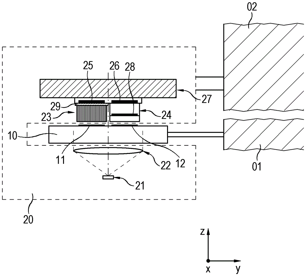
[0051] exist figure 1 shows a schematic cross-sectional view of an embodiment of a positioning device according to the present invention; in the following Figure 2-5 Other details of the device are shown in . Subsequently, this exemplary embodiment is explained with reference to various figures.

[0052] The positioning device according to the invention is used to determine the position of a first object O1 relative to a second object O2 that is movable relative to the first object O1 in at least one measuring direction x. In this case, one of the first objects O1 , for example the first machine part, is connected to a measuring standard 10 of the positioning device that extends along the measuring direction x. A further object O2 , for example a second machine part, is movable in the measuring direction x relative to the first machine part and is connected to the scanning unit 20 of the positioning device. In this embodiment, the relative movement of the two objects O1, O...


PUM


Abstract

An optical position-measuring device for determining the position of a first object relative to a second object movable relative to the first object along a measurement direction includes a scale with a measuring graduation connected to the first object and extending along the measurement direction. A scanner is connected to the second object and includes a fiber-optic array including optical fibers. The fiber-optic array is configured as a fiber-optic plate having an image-input face facing the scale and an image-output face facing the detector array. The fiber-optic array transmits a light pattern into a detection plane of the detector array. An interstitial medium is disposed between the image-output face of the fiber-optic plate and the detector array to ensure that an amount of deflection that the beams exiting the image-output face undergo on a path to the detector array is smaller than in a case without the interstitial medium.

Description

technical field [0001] The invention relates to an optical positioning device. The optical positioning device is suitable for determining the position of the first object relative to the second object. Background technique [0002] A positioning device of this type is known, for example, from EP 0 470 291 B1. The positioning device is used to determine the position of a first object relative to a second object which is arranged movable relative to the first object along at least one measuring direction. In this case, on the one hand, a scale is provided which extends along the first measuring direction and which is connected to the first object. The measuring scale comprises a measuring scale consisting of graduated areas with different optical properties arranged alternately along the measuring direction. On the other hand, a scanning unit is connected to the second object, said scanning unit comprising at least one light source, at least one detection device and at leas...

Claims


Application Information

Patent Timeline
IPC IPC(8): G01D5/38G01D5/347
CPCG01D5/34746G01D5/38G01D5/268G01D5/34715G01B11/14G01D5/26G01D5/28G01D5/347G01D5/353
Inventor W.霍尔茨阿普费尔C.林克U.本纳J.特劳特纳
Owner DR JOHANNES HEIDENHAIN GMBH
Learn More