A quality control method for dna ploidy analysis equipment

A quality control method and technology of analysis equipment, applied in the direction of analyzing materials, material analysis by optical means, measuring devices, etc., can solve the problems of inaccurate analysis results, and achieve the effect of accurate and error-free analysis of samples

Inactive Publication Date: 2020-03-10
黑龙江然得基尔医学科技发展有限公司
View PDF3 Cites 0 Cited by
  • Summary
  • Abstract
  • Description
  • Claims
  • Application Information

AI Technical Summary

Problems solved by technology

[0004] The purpose of the present invention is to propose a quality control method for DNA ploidy analysis equipment in order to solve the problem of inaccurate analysis results caused by equipment or sample problems in the prior art

Method used


Image

  • A quality control method for dna ploidy analysis equipment
  • A quality control method for dna ploidy analysis equipment
  • A quality control method for dna ploidy analysis equipment

Examples


specific Embodiment approach 1

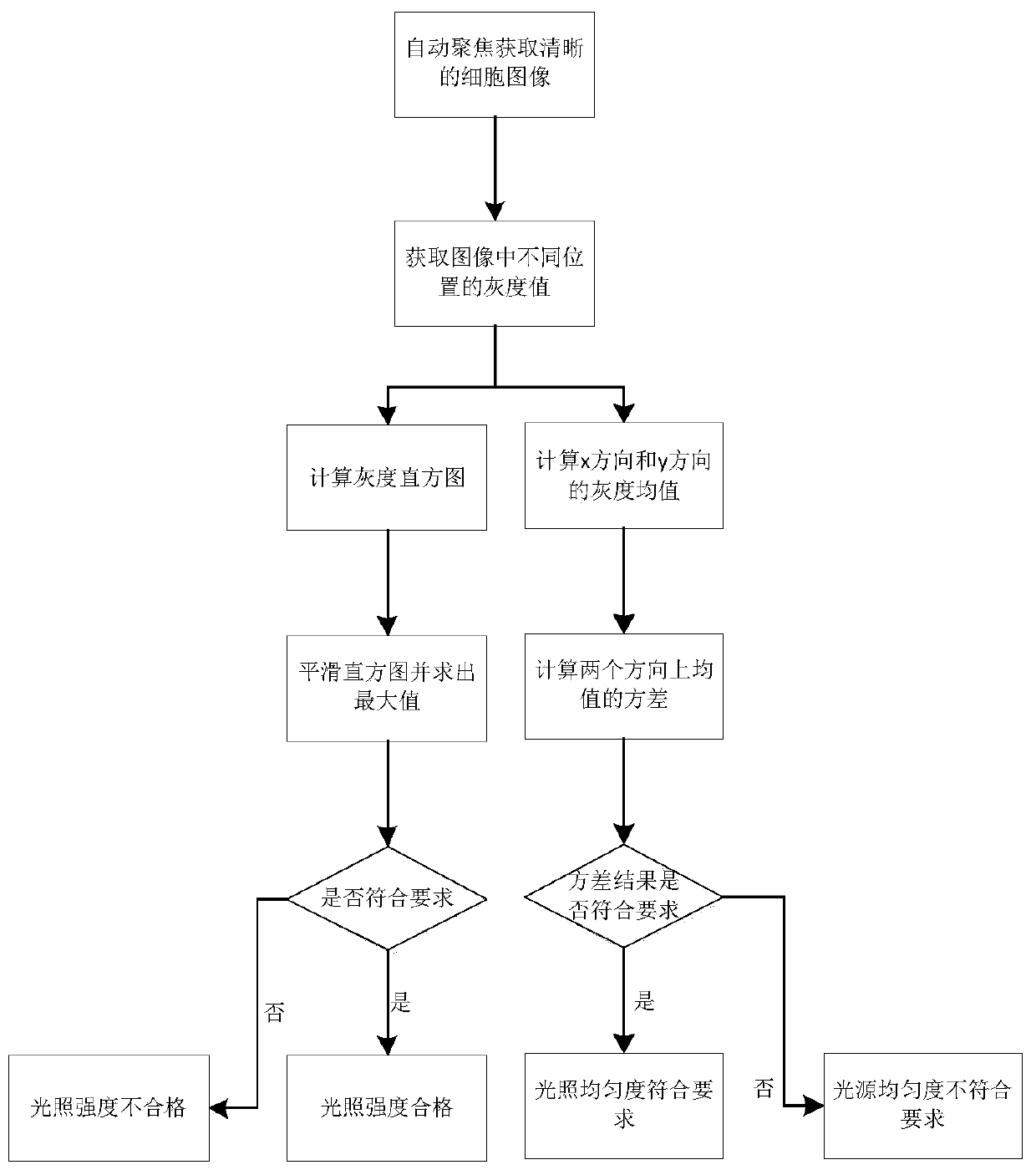
[0032] Specific embodiment one: a kind of quality control method of DNA ploid analysis equipment comprises the following steps:

[0033] Step 1: By analyzing the pictures under the microscope field of view, adjust the light source in the microscope to make the light intensity and light uniformity meet the requirements;

[0034] If T low ≤p max ≤T high Then the light intensity meets the requirements, where T low , T high Respectively represent the minimum and maximum values ​​of the light source intensity that meet the requirements, T low , T high After many experiments and theoretical explorations, it can make the equipment operate normally, keep the image from being too dark or too bright, which will affect the analysis of cells, and the results are within the allowable range of error, which will not lead to misdiagnosis and missed diagnosis. p max for p(p k ), the maximum value in p(p k ) is the mean value of the number of pixels corresponding to the gray level in th...

specific Embodiment approach 2

[0045] Specific embodiment 2: The difference between this embodiment and specific embodiment 1 is that in the step 1, by analyzing the pictures under the microscope field of view, the specific process of judging the intensity of illumination and the uniformity of illumination is as follows:

[0046] Step 11: Place the sample piece on the platform, and adjust the platform up and down to make a clear cell image under the camera field of view (the collected cell image has a clear outline, not blurred, not blurred, that is, the focus of the microscope objective lens coincides with the edge of the cell screen) ;

[0047] Step 1 and 2: Use the camera to capture the picture. Under the microscope, the black and white picture of the cell is represented by A0, and A0(i, j) represents the gray level at the image position (i, j), 1≤i≤M, 1≤j≤ N; M is the number of pixels in the horizontal direction in the captured image, and N is the number of pixels in the vertical direction in the captur...

specific Embodiment approach 3

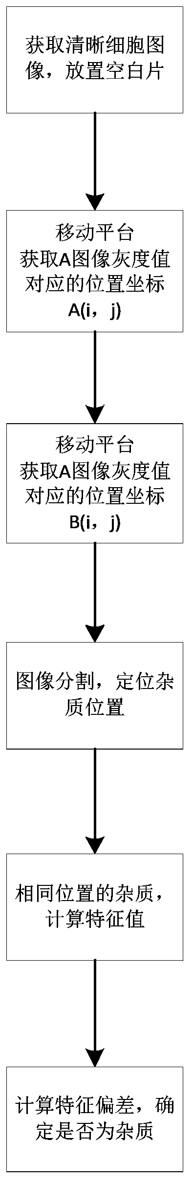
[0066] Specific embodiment three: the difference between this embodiment and specific embodiment one or two is that: in said step two, the specific process of determining the impurities in the optical path by analyzing the picture of the blank sheet under the microscope is:

[0067] Step 21: Place a blank slide and adjust the platform up and down to make a clear cell image in the camera field of view;

[0068] Step 2 and 2: Use the camera to capture the black and white picture under the microscope, represented by A, A(i, j) represents the gray value at the image position (i, j), 1≤i≤M, 1≤j≤N;

[0069] Step two and three: control the electric platform to move a field of view, and use the camera to collect picture B;

[0070] Step 2 and 4: Segment images A and B, and locate the impurity position; here the impurity may come from the optical path or from the blank film.

[0071] Step 25: Locate the position of the impurity on A and B. For the impurity at the same position on A an...


PUM


Abstract

The invention relates to a quality control method of DNA (Deoxyribonucleic Acid) ploidy analysis equipment. By adopting the quality control method of the DNA ploidy analysis equipment, the problem in the prior art that an analysis result is not accurate due to the problems of equipment or a sample is solved. The quality control method provided by the invention comprises the following steps: step 1, enabling illumination intensity and illumination uniformity to meet requirements; step 2: determining impurities in a light path through analyzing a picture of a blank slide under a microscope and carrying out impurity removal treatment; step 3: judging whether the equipment is at a normal working state or not; step 4: judging whether a sample slide of a patient is dyed uniformly or not; step 5: after determining a calibration zero point used in a microscope focusing process by utilizing a three-point fixed-point focusing manner, calculating positions of cells, relative to the calibration zero point, on a microscope slide in each view field through counting up movement distances of a control focusing platform; drawing a three-dimensional line graph; adjusting a microscope platform according to the three-dimensional line graph. The quality control method of the DNA ploidy analysis equipment is used for the field of instrument analysis.

Description

technical field [0001] The invention relates to a quality control method of DNA ploid analysis equipment. Background technique [0002] In recent years, malignant tumors have been at a high incidence in my country. According to statistics, about 7 people are diagnosed with malignant tumors every minute in our country. This has become the most important cause of fatality rate in our country, which has aroused great concern of governments at all levels. Taking cervical cancer as an example, it is the third most common malignant tumor in women in the world and the second most common malignant tumor in Chinese women. According to the estimates of the World Health Organization (WHO), there are more than 470,000 new cases of cervical cancer in the world every year, and China accounts for 28%. Early diagnosis and early treatment is an effective way to deal with the high incidence of cancer. Pathologists collect human exfoliated cells, including cervical exfoliated cells, punctur...

Claims


Application Information

Patent Timeline
Patent Type & Authority Patents(China)
IPC IPC(8): G01N21/17
CPCG01N21/17
Inventor 陈兴路
Owner 黑龙江然得基尔医学科技发展有限公司
Why Eureka
Try Eureka