STO bias control for mamr head reliability

A controller, bias current technology, applied in the direction of head configuration, recording head configuration/installation, head winding configuration, etc., can solve problems such as damage to STO performance, heat generation, etc.

Active Publication Date: 2019-10-29
WESTERN DIGITAL TECH INC
View PDF5 Cites 0 Cited by
  • Summary
  • Abstract
  • Description
  • Claims
  • Application Information

AI Technical Summary

Problems solved by technology

However, this constant application of DC on the STO results in significant heat generation, thereby also compromising the STO performance

Method used


Image

  • STO bias control for mamr head reliability
  • STO bias control for mamr head reliability
  • STO bias control for mamr head reliability

Examples


Embodiment Construction

[0017] Selected embodiments of the present disclosure will now be described with reference to the accompanying drawings. It will be apparent to those skilled in the art from this disclosure that the following descriptions of the embodiments of the present disclosure are provided for illustration only and not for the purpose of limiting the invention as defined by the appended claims and their equivalents.

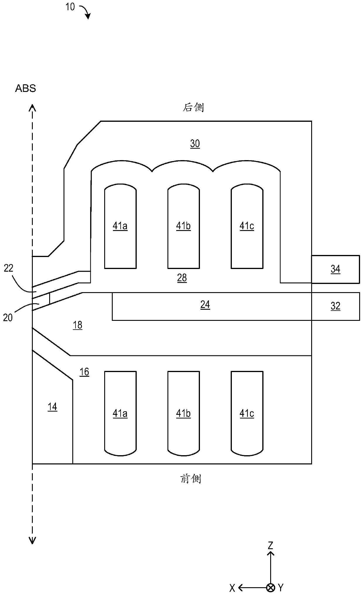
[0018] The present disclosure is directed to a magnetic field assisted magnetic recording (MAMR) head with a spin torque oscillator (STO), for magnetic recording systems such as figure 1 The disk drive shown in the figure 2 An example of this is shown at the beginning.

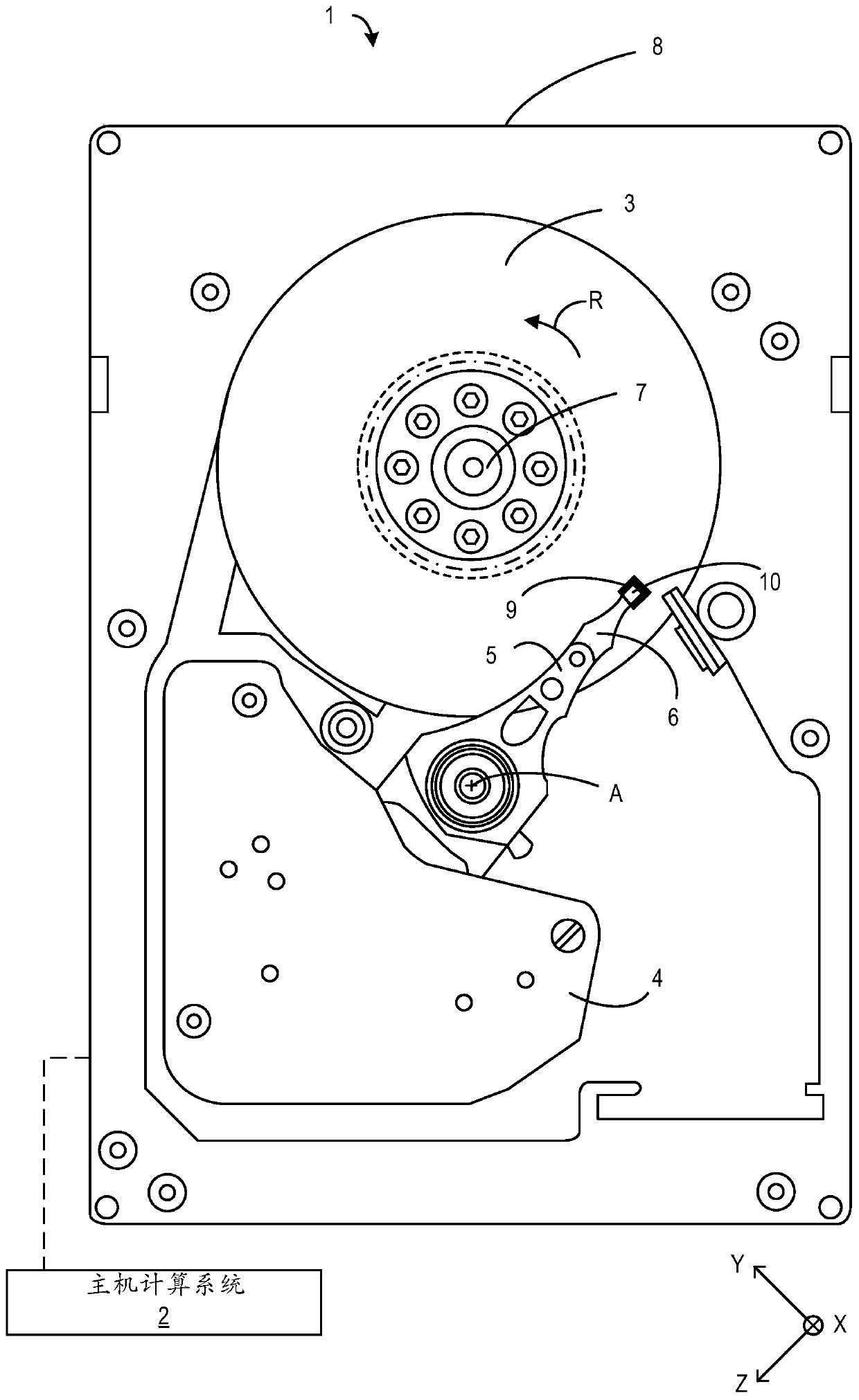
[0019] first go to figure 1 , which shows a top view of an exemplary hard disk drive (HDD) 1 into which a magnetic field assisted magnetic recording (MAMR) head 10 of the present disclosure may be incorporated, according to an embodiment of the present disclosure. HDD 1 is a magnetic recording device co...


PUM


Abstract

The MAMR head includes a main magnetic pole, a spin torque oscillator (STO) positioned above the main magnetic pole, and a write coil coupled to the main magnetic pole. The STO generates a high-frequency magnetic field on the magnetic medium. The controller is configured to provide a first bias current at a first bias current level to the STO and further provide a second bias current at a second bias current level to the STO. The controller is further configured to time the second bias current to coincide with a current overshoot within the write coil.

Description

[0001] Background of the invention [0002] The present disclosure relates to a spin torque oscillator (STO) in a magnetic field assisted recording (MAMR) head, wherein the spin torque oscillator is formed in a writing gap and a high frequency magnetic field is applied to a recording medium to reduce the coercivity of the medium force, and apply a recording field to the medium in this state to record data. One challenge with conventional MAMR heads is that current overshoot in the write coil coupled to the main pole raises the switching field threshold within the magnetic medium, resulting in insufficient MAMR assist gain for adequate record width and good write capability . Conventional pulse assist techniques in MAMR heads do not adequately address MAMR assist gain reduction associated with current overshoot in the write coil. [0003] Another challenge of conventional spin-torque oscillators is that the small size of STOs is associated with significantly higher bias heat be...

Claims


Application Information

Patent Timeline
Patent Type & Authority Patents(China)
IPC IPC(8): G11B5/48G11B5/31
CPCG11B5/3109G11B5/488G11B5/02G11B5/17G11B2005/0024
Inventor 田中秀明渡边克朗田所茂木村亘丸山洋治
Owner WESTERN DIGITAL TECH INC
Why Eureka
Try Eureka