Supercharge Your Innovation With Domain-Expert AI Agents!

Honeycomb structure with crack resistance

A structure and honeycomb technology, applied in the direction of catalyst carrier, physical/chemical process catalyst, lighting and heating equipment, etc., can solve problems such as thermal shock and crack generation, and achieve the effect of inhibiting the generation and expansion of cracks

Active Publication Date: 2019-11-22
ENBION
View PDF8 Cites 0 Cited by
  • Summary
  • Abstract
  • Description
  • Claims
  • Application Information

AI Technical Summary

Problems solved by technology

But the problem is that due to the high brittleness of silicon carbide, cracks will inevitably occur during the molding and drying process when the capacity is increased, and it will be subjected to thermal shock caused by repeated heating and cooling in a high-temperature operating environment.

Method used


Image

  • Honeycomb structure with crack resistance
  • Honeycomb structure with crack resistance
  • Honeycomb structure with crack resistance

Examples


Embodiment Construction

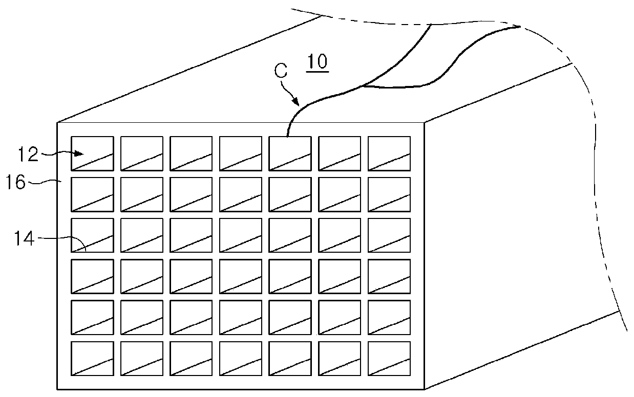
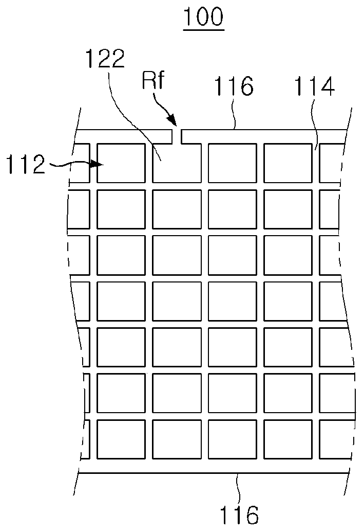
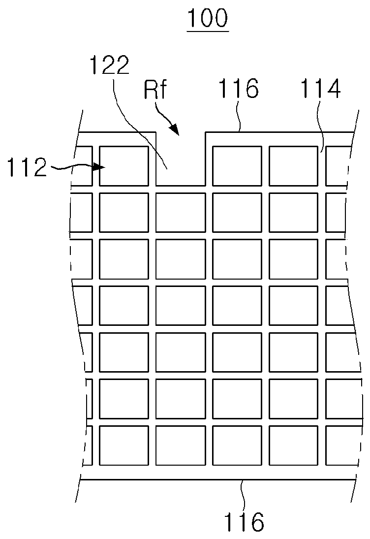
[0058] image 3 It is a figure which shows roughly the cross-sectional structure of the honeycomb structure of the 2nd Example of this invention.

[0059] image 3 The residual stress relaxation feature Rf of Rf is another realization form of the outer wall longitudinal section. In this embodiment, one chamber unit has no outer wall and is exposed to the outside. In this configuration, the residual stress relaxation features also still interrupt the continuity of the left and right outer walls of the cell unit.

[0060] image 3 The method of forming the outer wall longitudinal section by exposing one chamber unit is shown, but those of ordinary skill in the art to which the present invention pertains to who is exposed to the present invention can understand that two or more adjacent in a direction parallel to the outer wall surface may be formed. The chamber unit or two or more chamber units adjacent in the direction perpendicular to the outer wall surface are exposed in ...


PUM


Abstract

The invention discloses a honeycomb structure with high crack resistance. The present invention provides a honeycomb structure, comprising a plurality of cell units extending in the length direction and divided by partition walls in order to provide passages for fluid flow, characterized in that the honeycomb structure includes The outer wall of the shaped structure, at least a portion of the outer wall has a stress relief feature. According to the present invention, it is possible to provide a scalable honeycomb structure while effectively suppressing the generation and propagation of cracks.

Description

technical field [0001] The present invention relates to a honeycomb structure, and more particularly, to a honeycomb structure with high crack resistance. Background technique [0002] In general, a honeycomb structure is a structure formed in a honeycomb shape from a plurality of cell units for fluid flow, and can be used for various purposes such as heat storage materials, diesel particulate filters (DPF), catalyst carriers, and the like. [0003] Honeycomb structures based on ceramic materials are produced by molding methods such as extrusion and injection molding. However, during the drying process after molding, there is a problem that it is difficult to expand into a large-capacity honeycomb structure due to cracks on the surface of the structure. Due to such a problem, although a method of stacking and sticking small honeycomb structures for modularization is used for large-capacity fluid flow, this method requires the design of additional processes such as stacking a...

Claims


Application Information

Patent Timeline
Patent Type & Authority Patents(China)
IPC IPC(8): F01N3/022F01N3/28F28D20/00B01J32/00
CPCF01N3/022F01N3/28F16S3/00
Inventor 李贤宰肯恩·奥伦
Owner ENBION
Features
  • R&D
  • Intellectual Property
  • Life Sciences
  • Materials
  • Tech Scout
  • Unparalleled Data Quality
  • Higher Quality Content
  • 60% Fewer Hallucinations
Learn More