Liquid taking member used for enclosed body fluid retention device

A body fluid and ring-shaped technology, applied in the field of medical devices, can solve the problems of complex production and processing, high cost, and low production efficiency, and achieve the effects of shortening processing time, reducing preparation costs, and reducing mechanisms

Inactive Publication Date: 2018-01-05
WUXI KAISHUN MEDICAL DEVICE MFG CO LTD
View PDF12 Cites 1 Cited by
  • Summary
  • Abstract
  • Description
  • Claims
  • Application Information

AI Technical Summary

Problems solved by technology

Even if the liquid taking part is equipped with an exhaust channel, during the liquid guiding process, the liquid will still flow to the exhaust port to block the exhaust port, resulting in liquid retention
In addition, the liquid extraction part is equipped with an exhaust channel, but the production and processing are more complicated, the cost is high, the production efficiency is low, and the speed of diversion is not fast enough

Method used


Image

  • Liquid taking member used for enclosed body fluid retention device
  • Liquid taking member used for enclosed body fluid retention device
  • Liquid taking member used for enclosed body fluid retention device

Examples


Embodiment 1

[0053] Embodiment 1: below in conjunction with attached figure 1 to attach Figure 5 , Figure 11 The present invention is described further:

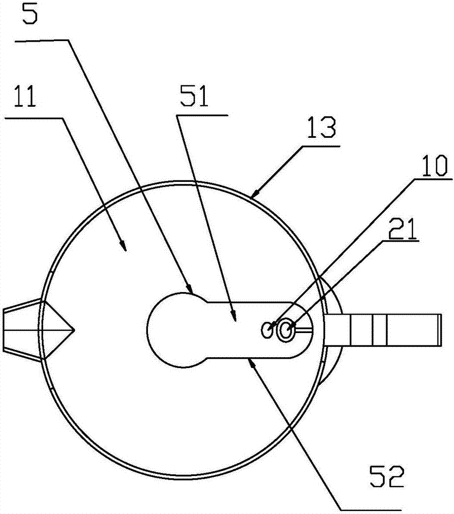
[0054] A liquid-taking part for a closed body fluid indwelling device, comprising an annular side wall A1 and an annular side wall B2.

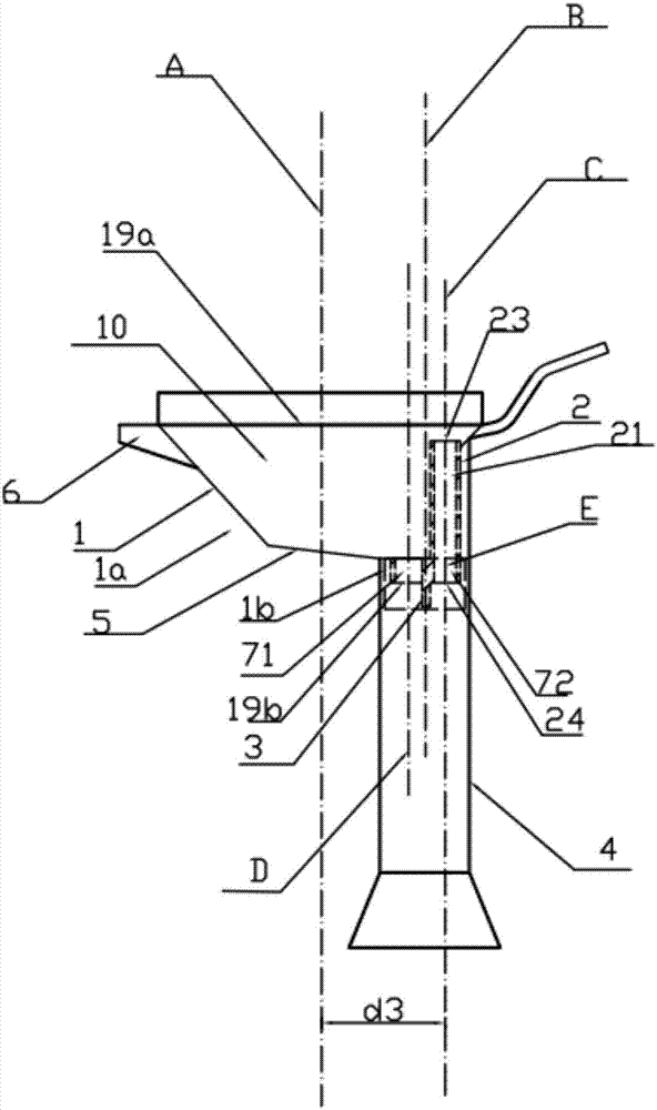
[0055] The annular side wall armor 1 has an upper opening 11 and a lower opening 12 . The annular side wall armor 1 includes an upper portion 1a of the annular side wall armor, a bottom sealing plate 5 and a lower portion 1b of the annular side wall armor. The annular side wall A 1 encloses and forms a guide channel 10 . The liquid guiding channel 10 has a liquid inlet 19a and a liquid outlet 19b. The upper part 1a of the annular side wall is used to collect liquid, the lower part 1b of the annular side wall is used to cooperate with the test tube, and the bottom sealing plate 5 is connected with the upper part 1a of the annular side wall and the lower part 1b of the annular side wall respectivel...

Embodiment 2

[0073] Embodiment 2: below in conjunction with attached Image 6 to attach Figure 10 , Figure 12 The present invention is described further:

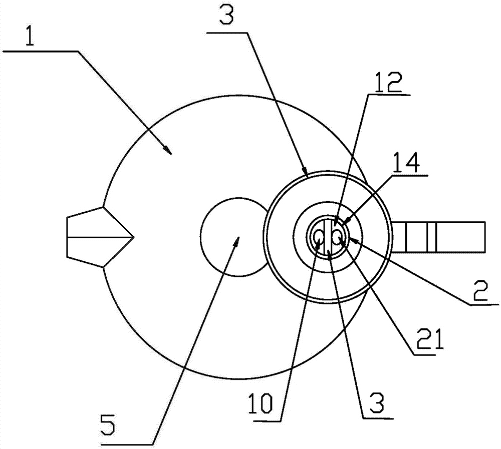
[0074] A liquid-taking part for a closed body fluid indwelling device, comprising an annular side wall A1 and an annular side wall B2.

[0075] The annular side wall armor 1 has an upper opening 11 and a lower opening 12 . The annular side wall armor 1 includes an upper portion 1a of the annular side wall armor, a bottom sealing plate 5 and a lower portion 1b of the annular side wall armor. The annular side wall A 1 encloses and forms a guide channel 10 . The liquid guiding channel 10 has a liquid inlet 19a and a liquid outlet 19b. The upper part 1a of the annular side wall is used to collect liquid, the lower part 1b of the annular side wall is used to cooperate with the test tube, and the bottom sealing plate 5 is connected with the upper part 1a of the annular side wall and the lower part 1b of the annular side wall respective...

Embodiment 3

[0086] Embodiment 3: below in conjunction with attached Image 6 , Figure 7 , Figure 8 , Figure 12 , Figure 13 , Figure 14 The present invention is described further:

[0087] A liquid-taking part for a closed body fluid indwelling device, comprising an annular side wall A1 and an annular side wall B2.

[0088] The annular side wall armor 1 has an upper opening 11 and a lower opening 12 . The annular side wall armor 1 includes an upper portion 1a of the annular side wall armor, a bottom sealing plate 5 and a lower portion 1b of the annular side wall armor. The annular side wall A 1 encloses and forms a guide channel 10 . The liquid guiding channel 10 has a liquid inlet 19a and a liquid outlet 19b. The upper part 1a of the annular side wall is used to collect liquid, the lower part 1b of the annular side wall is used to cooperate with the test tube, and the bottom sealing plate 5 is connected with the upper part 1a of the annular side wall and the lower part 1b of ...


PUM


Abstract

The invention relates to a medical apparatus, and especially relates to an apparatus used for acquiring body fluid. A liquid taking member used for an enclosed body fluid retention device comprises afirst annular side wall and a second annular side wall. The first annular side wall is provided with an upper opening and a lower opening. The second annular side wall is in a straight tube shape. Thelower part of the second annular side wall is in the lower opening. The lower part of the first annular side wall and the lower part of the second annular side wall have a common side wall. The upperpart of the second annular side wall is adjacent to the upper part of the first annular side wall. A shortest segment which is vertical to the second annular side wall is connected with the top end of the first annular side wall. Length of the shortest segment is not larger than that of an extension line of the shortest segment, or 35% length of a longest segment which is formed by intersecting aline parallel with the shortest segment and the top end of an inner edge of the first annular side wall. The liquid taking member is advantaged by simple processing and high production efficiency, and reducing production cost and preventing backflow.

Description

technical field [0001] The present invention relates to medical devices, and more particularly to devices for collecting body fluids. Background technique [0002] The liquid-taking part of the prior art airtight body fluid indwelling device only has a diversion channel and does not have an exhaust channel. Especially when liquid is poured into a small-caliber container, when the liquid-taking part is sealed with the connection of the container, the retention of liquid often occurs. Even if the liquid taking part is provided with an exhaust channel, during the liquid guiding process, the liquid will still flow to the exhaust port to block the exhaust port, resulting in liquid retention. In addition, the liquid taking part is provided with an exhaust channel, but the production process is complicated, the cost is high, the production efficiency is low, and the speed of diversion is not fast enough. Contents of the invention [0003] The object of the present invention ...

Claims


Application Information

Patent Timeline
Patent Type & Authority Applications(China)
IPC IPC(8): A61B10/00
Inventor 不公告发明人
Owner WUXI KAISHUN MEDICAL DEVICE MFG CO LTD
Why Eureka
Try Eureka