
Noise reduction device, compressor and air conditioner

A compressor and noise reduction technology, applied in the direction of machines/engines, parts of pumping devices for elastic fluids, mechanical equipment, etc., to reduce impact, vibration and noise

Pending Publication Date: 2018-01-05
GREE ELECTRIC APPLIANCES INC OF ZHUHAI
View PDF7 Cites 16 Cited by
  • Summary
  • Abstract
  • Description
  • Claims
  • Application Information

AI Technical Summary

Problems solved by technology

[0008] To sum up, it can be seen that in the prior art, the airflow energy is mostly passively reduced to achieve the shock absorption effect or the natural frequency of the relevant pipeline and the gas column are adjusted to avoid the resonance frequency region. There is no device in the prior art that is Actively attenuate the airflow pulsation of the compressor from the source, thereby reducing the impact of noise and vibration

Method used


Image

  • Noise reduction device, compressor and air conditioner
  • Noise reduction device, compressor and air conditioner
  • Noise reduction device, compressor and air conditioner

Examples


Embodiment Construction

[0029] It should be noted that, in the case of no conflict, the embodiments in the present application and the features in the embodiments can be combined with each other. The present invention will be described in detail below with reference to the accompanying drawings and examples.

[0030] It should be pointed out that the following detailed description is exemplary and intended to provide further explanation to the present application. Unless defined otherwise, all technical and scientific terms used herein have the same meaning as commonly understood by one of ordinary skill in the art to which this application belongs.

[0031] The following will clearly and completely describe the technical solutions in the embodiments of the present invention with reference to the accompanying drawings in the embodiments of the present invention. Obviously, the described embodiments are only some, not all, embodiments of the present invention. The following description of at least on...


PUM


Abstract

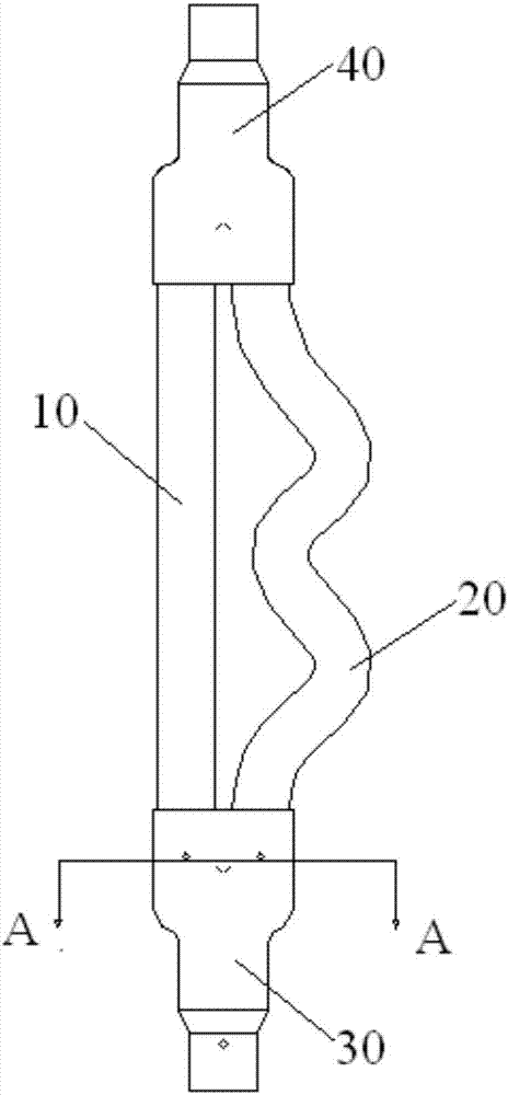
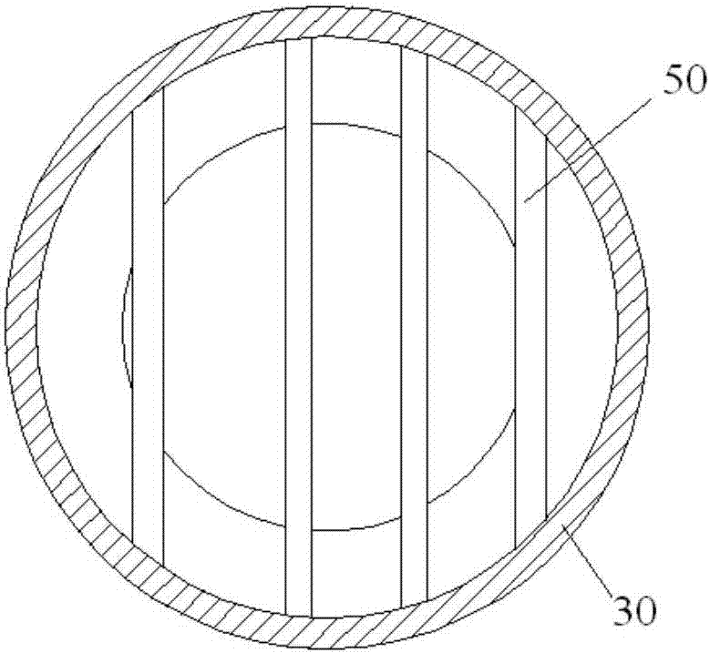
The invention provides a noise reduction device, a compressor and an air conditioner. The noise reduction device is arranged at an exhaust port of the compressor; the noise reduction device comprisesa main flow pipeline, one or more side branch pipelines, wherein along the flowing direction of air flow, the outlet end of the main flow pipeline communicates with the outlet end of each side branchpipeline; a waveform of air flow flowing through the main flow pipeline and a waveform of air flow flowing through the at least one side branch pipeline have a phase difference so as to reduce an amplitude value of a waveform of converged air flow. The noise reduction device disclosed by the invention can actively attenuate the pulse of the air flow so as to reduce noise.

Description

technical field [0001] The invention relates to the technical field of air conditioners, in particular to a noise reduction device, a compressor and an air conditioner. Background technique [0002] The vibration and noise of the refrigeration unit is an important factor affecting the reliability and user experience of the unit. At present, the main vibration causes are divided into two parts: one is that the mechanical vibration of the compressor body is transmitted to the unit. Due to the poor dynamic balance of the moving parts of the compressor itself, misalignment, improper foundation design, etc., it can cause the vibration of the unit, thereby causing the pipeline connected to it to vibrate; on the other hand, the exhaust gas of the compressor is in the pipeline Create air pulsation. If the compressor produces pressure changes during the exhaust process or due to the intermittent and periodic suction and exhaust of the unit during operation, these conditions will ar...

Claims


Application Information

Patent Timeline
IPC IPC(8): F04C29/06F24F13/24
Inventor 张磊张威何林罗建飞
Owner GREE ELECTRIC APPLIANCES INC OF ZHUHAI
Features
  • Generate Ideas
  • Intellectual Property
  • Life Sciences
  • Materials
  • Tech Scout
  • Unparalleled Data Quality
  • Higher Quality Content
  • 60% Fewer Hallucinations
Learn More