Angle sensor and angle sensor system
An angle sensor and angle technology, which is applied in converting sensor output, using electric/magnetic devices to transmit sensor components, instruments, etc., can solve problems such as the inability to reduce the angle error of higher harmonics, and the difficulty of designing magnetoresistive effect elements.
- Summary
- Abstract
- Description
- Claims
- Application Information
AI Technical Summary
Problems solved by technology
Method used
Image
Examples
no. 1 approach
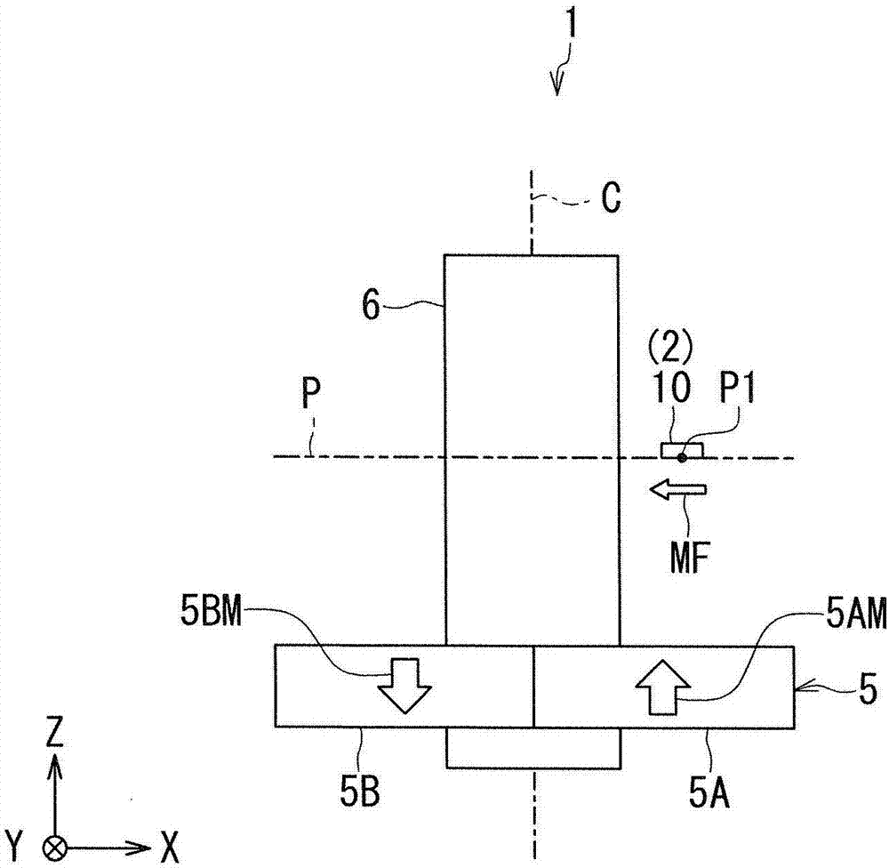
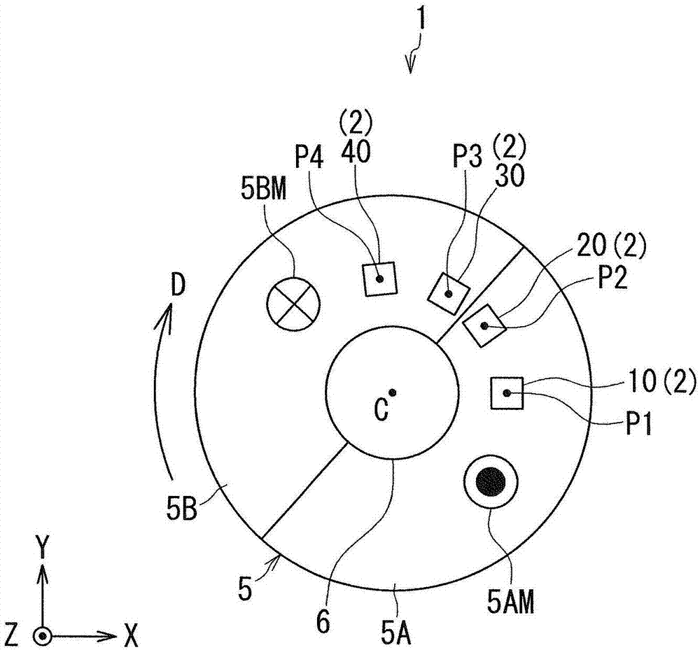
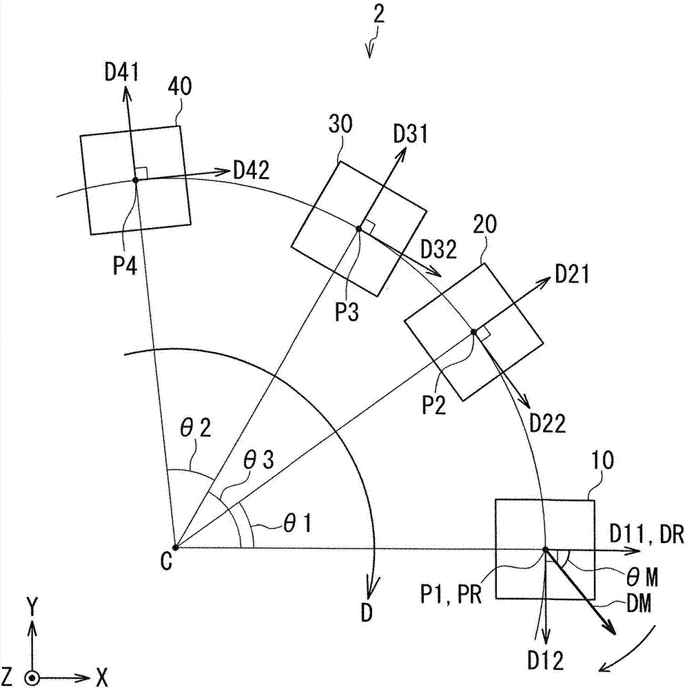
[0061] Hereinafter, embodiments of the present invention will be described in detail with reference to the drawings. First, refer to figure 1 and figure 2A schematic configuration of the angle sensor system according to the first embodiment of the present invention will be described. The angle sensor system 1 according to the present embodiment includes the angle sensor 2 according to the present embodiment. The angle sensor 2 according to the present embodiment is particularly a magnetic angle sensor. Such as figure 1 and figure 2 As shown, the angle sensor system 1 further includes a magnetic field generator 5 that generates a rotating magnetic field MF that rotates in direction. The angle sensor 2 generates an angle detection value corresponding to an angle formed by the direction of the rotating magnetic field MF at the reference position with respect to the reference direction. Hereinafter, the angle formed by the direction of the rotating magnetic field MF at the...
no. 1 example 1
[0192] As in the first embodiment, when the first and second detection signals S1 and S2 are represented by equations (1) and (2) respectively, in the second embodiment, the third and fourth detection signals S3 and S4 can be respectively represented by the following formulas (9) and (10).
[0193] S3=cos(θ+360° / n)
[0194] +a 1 ·cos{n(θ+360° / n)}
[0195] +b 1 ·cos{m(θ+360° / n)}
[0196] =cos(θ+360° / n)
[0197] +a 1 ·cos(nθ+360°)
[0198] +b 1 ·cos{m(θ+360° / n)}
[0199] =cos(θ+360° / n)
[0200] +a 1 ·cos(nθ)
[0201] +b 1 ·cos{m(θ+360° / n)}...(9)
[0202] S4=sin(θ+360° / n)
[0203] +a 2 · sin{n(θ+360° / n)}
[0204] +b 2 · sin{m(θ+360° / n)}
[0205] =sin(θ+360° / n)
[0206] +a 2 · sin(nθ+360°)
[0207] +b 2 · sin{m(θ+360° / n)}
[0208] =sin(θ+360° / n)
[0209] +a 2 · sin(nθ)
[0210] +b 2 · sin{m(θ+360° / n)}…(10)
[0211] In addition, the fifth and sixth detection signals S5 and S6 can be represented by the following equations (11) and (12), respectively.
[...
no. 2 approach
[0317] Next, a second embodiment of the present invention will be described. First, refer to Figure 13 A schematic configuration of an angle sensor system according to this embodiment will be described. The angle sensor system 1 according to this embodiment differs from the first embodiment in the following points. The angle sensor system 1 according to the present embodiment includes a magnetic field generating unit 7 instead of the magnetic field generating unit 5 in the first embodiment. The magnetic field generator 7 in the present embodiment is a cylindrical magnet, and generates a rotating magnetic field MF whose direction is rotated. The magnetic field generator 7 rotates in the rotation direction D around the center axis C. As shown in FIG.
[0318] The magnetic field generator 7 includes first and second portions 7A, 7B whose magnetization directions are different from each other. The first and second portions 7A, 7B are arranged symmetrically about an imaginary ...
PUM
 Abstract
Description
Claims
Application Information
 - R&D
- Intellectual Property
- Life Sciences
- Materials
- Tech Scout
- Unparalleled Data Quality
- Higher Quality Content
- 60% Fewer Hallucinations
Browse by: Latest US Patents, China's latest patents, Technical Efficacy Thesaurus, Application Domain, Technology Topic, Popular Technical Reports.
© 2025 PatSnap. All rights reserved.Legal|Privacy policy|Modern Slavery Act Transparency Statement|Sitemap|About US| Contact US: help@patsnap.com


