
A method and system for suppressing vibration of a mechanically moving structure

A technology of structural vibration and mechanical motion, applied in general control systems, control/regulation systems, adaptive control, etc., can solve the problems of easily affecting the response speed of the system, increase the time delay of the system, increase the control cost, etc., to avoid high-speed operation. Vibration increase phenomenon, avoid response time lag, cost saving effect

Active Publication Date: 2020-09-01
BEIHANG UNIV
View PDF7 Cites 0 Cited by
  • Summary
  • Abstract
  • Description
  • Claims
  • Application Information

AI Technical Summary

Problems solved by technology

However, these control methods have shortcomings
Using methods such as increasing system damping and increasing structural rigidity will increase the overall weight of the system, increase the energy consumption of the system, and easily affect the response speed of the system
Using the PID control method requires changing the control structure of the system and adding sensor equipment, which increases the complexity of the control system and increases the control cost
Ordinary input shaping usually increases the time lag of the system and reduces the response speed of commands

Method used


Image

  • A method and system for suppressing vibration of a mechanically moving structure
  • A method and system for suppressing vibration of a mechanically moving structure
  • A method and system for suppressing vibration of a mechanically moving structure

Examples


Embodiment Construction

[0046] The present invention will be described in more detail below with reference to the accompanying drawings. Although preferred embodiments of the invention are shown in the drawings, it should be understood that the invention may be embodied in various forms and should not be limited to the embodiments set forth herein. Rather, these embodiments are provided so that this disclosure will be thorough and complete, and will fully convey the scope of the invention to those skilled in the art.

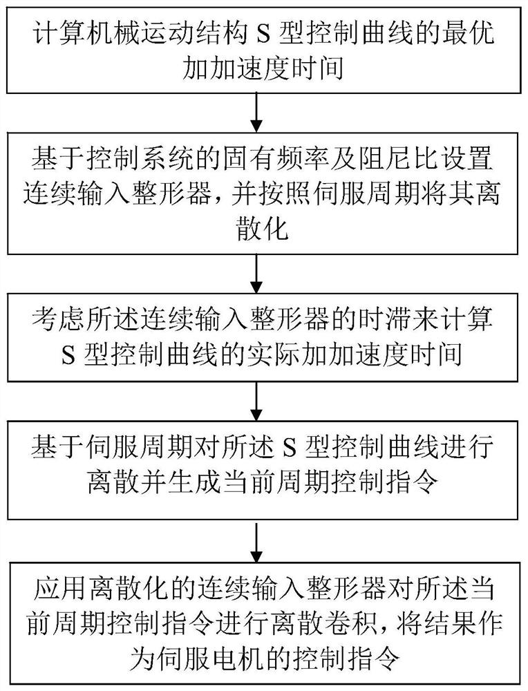
[0047] The following reference figure 1 The method for suppressing the vibration of a mechanical moving structure according to the present invention is described in detail. The method mainly includes:

[0048] Step 1: Calculate the optimal jerk time of the S-shaped control curve of the mechanical motion structure.

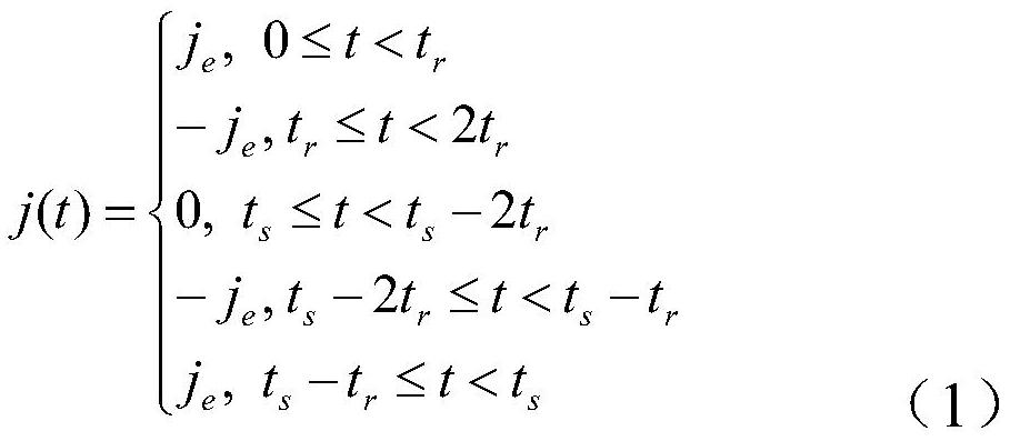
[0049] In one example, the S-shaped control curve is a five-segment S-shaped control curve, the formula of which is:

[0050]

[0051] Among them, j e is the jerk v...


PUM


Abstract

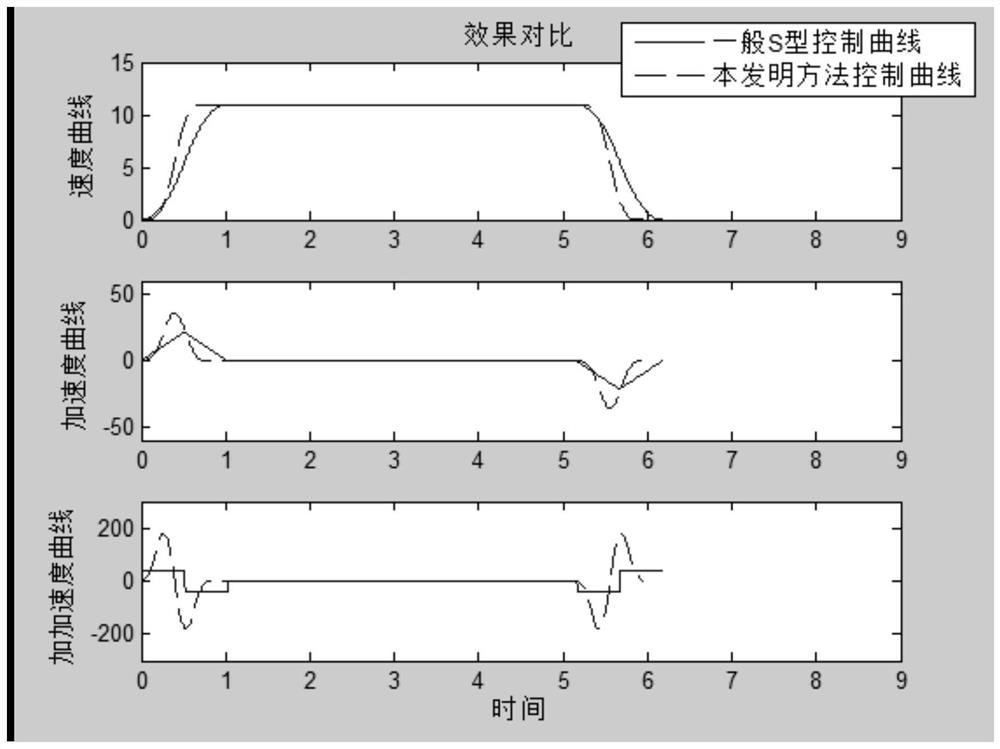
The invention discloses a method and system for suppressing the vibration of a mechanical motion structure. The method comprises the steps of (1) calculating an optimal jerk time of an S control curveof the mechanical motion structure, (2) setting a continuous input shaper based on a natural frequency and a damping ratio of a control system and discretizing the continuous input shaper according to a servo period, (3) calculating an actual jerk time of the S control curve with the consideration of a time lag of the continuous input shaper, (4) discretizing the S control curve based on the servo period and generating a current period control instruction, and (5) applying the discretized continuous input shaper in the step (2) to carry out discrete convolution on the current period control instruction, and taking a result as a control command of the servo motor. According to the method and the system, a phenomenon of high-speed running vibration aggravation generated in general input shaping is avoided, based on original control, the adding of hardware equipment is not needed, and the cost is saved.

Description

technical field [0001] The invention relates to the technical field of mechanical control, and more specifically, to a method and system for suppressing vibration of a mechanical moving structure. Background technique [0002] Motor-driven mechanical motion structures including industrial robots, CNC machine tools, and CNC mechanical structures have requirements for high speed, high precision, and high stability. Due to the existence of transmission components such as reducers or pulleys, mechanical motion structures usually have a certain degree of flexibility. During low-speed operation and start and stop stages, the end of the mechanical movement structure will vibrate. The vibration of the mechanical structure will not only reduce the response speed of the system to commands, but also increase the waiting time between processes, reducing production efficiency and precision. Therefore, effective measures must be taken to suppress the vibration of the mechanical moving s...

Claims


Application Information

Patent Timeline
Patent Type & Authority Patents(China)
IPC IPC(8): G05B13/04
Inventor 陈友东刘重续
Owner BEIHANG UNIV
Learn More