Rotor, motor and washing machine

A washing machine and rotor technology, applied in the field of washing machines, can solve the problems of affecting the motor control response time, increasing the difficulty of rotor dynamic balance, complex structure and process realization, etc., so as to reduce the risk of product balance failure, promote the simplification of product structure, The effect of saving product consumables and costs

Pending Publication Date: 2020-03-03
WUXI LITTLE SWAN ELECTRIC CO LTD
View PDF14 Cites 1 Cited by
  • Summary
  • Abstract
  • Description
  • Claims
  • Application Information

AI Technical Summary

Problems solved by technology

[0003] In the process of realizing the present invention, the inventor found that the prior art has the following disadvantages: On the one hand, the rotor end ring structure needs to be installed with fasteners or a special injection molding or cast aluminum mold is used for the end ring on the rotor core. Ring forming, the structure and process are complicated; on the other hand, the end ring structure increases the weight of the rotor, and it is easy to cause the imbalance of the weight of the rotor itself, which increases the difficulty of dynamic balancing of the rotor, and also increases the moment of inertia of the rotor, which affects the control of the motor. Response time

Method used


Image

  • Rotor, motor and washing machine
  • Rotor, motor and washing machine
  • Rotor, motor and washing machine

Examples


Embodiment Construction

[0035] In order to understand the above-mentioned purpose, features and advantages of the present invention more clearly, the present invention will be further described in detail below in conjunction with the accompanying drawings and specific embodiments. It should be noted that, in the case of no conflict, the embodiments of the present application and the features in the embodiments can be combined with each other.

[0036] In the following description, many specific details are set forth in order to fully understand the present invention. However, the present invention can also be implemented in other ways different from those described here. Therefore, the protection scope of the present invention is not limited by the specific details disclosed below. EXAMPLE LIMITATIONS.

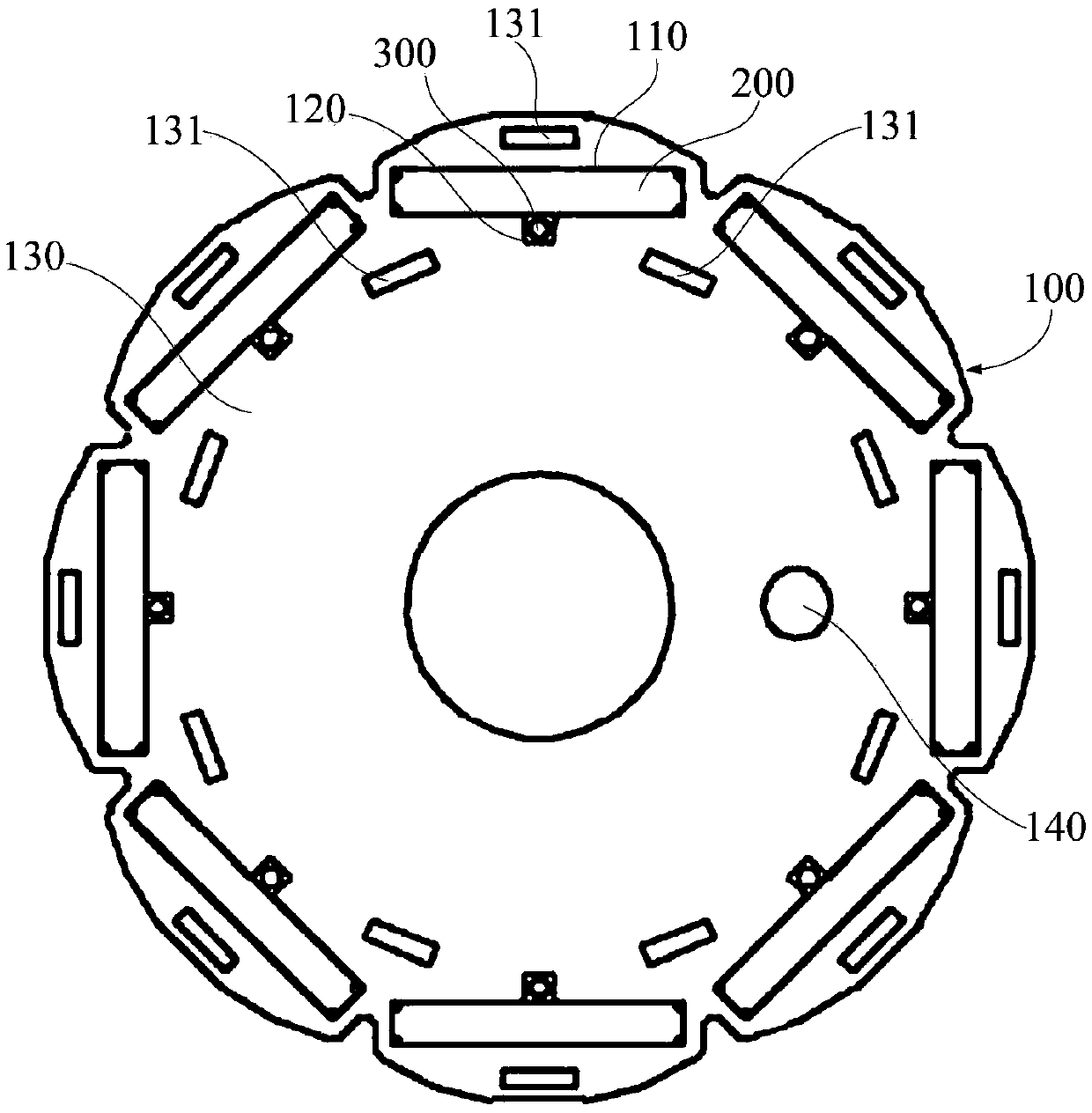
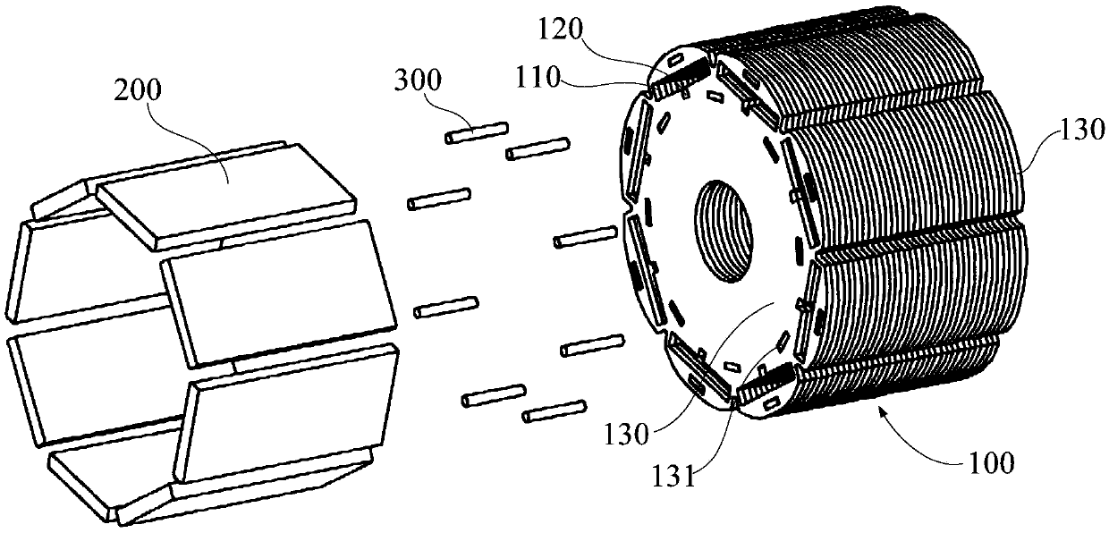
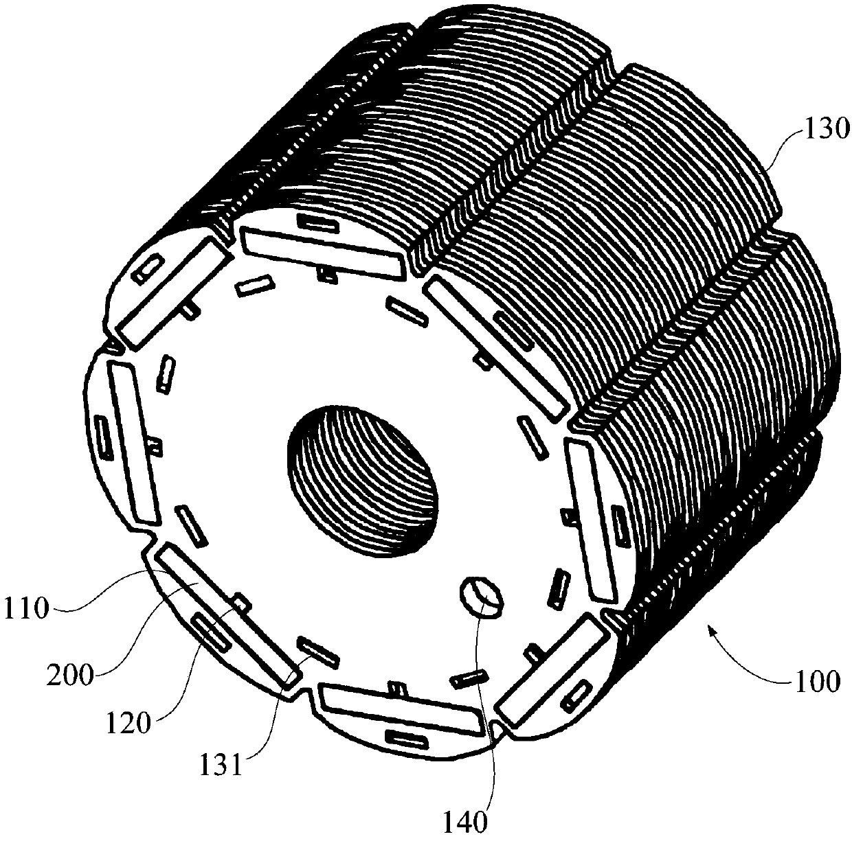
[0037] Refer below Figure 1 to Figure 3 The rotor according to some embodiments of the invention is described.

[0038] like figure 1 and figure 2 As shown, the rotor provided by the embodiment...


PUM


Abstract

The invention provides a rotor, a motor and a washing machine. The rotor comprises a rotor core, a magnetic steel and a rivet, wherein the rotor core is provided with a magnetic steel groove and a rivet hole; the magnetic steel is arranged in the magnetic steel groove; and the rivet is connected to the rivet hole and limits the magnetic steel in the magnetic steel groove. According to the rotor provided in the scheme, the magnetic steel is directly limited and fixed in the magnetic steel groove of the rotor core by the rivet; in comparison with the scheme of limiting and fixing the magnetic steel through a fastener or an end ring fixed on the rotor core through injection molding or cast aluminum in the prior art, while the magnetic steel is reliably installed, the whole product is of an end-ring-free structure on the whole, the assembly steps are few, rotor injection molding or aluminum cast operation is not needed, and the production process of products is greatly simplified; the total weight of the rotor is also reduced correspondingly; the advantages of small rotational inertia and good motor starting performance are achieved; and the problems of unbalanced self-weight of the rotor and the like caused by end rings can be prevented, dynamic balance of the product can be realized more easily, and the risk of balance failure of the product is reduced.

Description

technical field [0001] The invention relates to the field of motors, in particular to a rotor, a motor and a washing machine. Background technique [0002] The rotor structure of the existing built-in permanent magnet motor is as follows: the magnetic steel is installed in the rotor iron core, and the magnetic steel is fixed by the end ring after positioning by the magnetic steel glue or fixed by injection molding or cast aluminum. In addition, the aluminum The rotor is dynamically balanced by de-weighting or adding weight to the end ring made of solid or plastic material. [0003] In the process of realizing the present invention, the inventor found that the prior art has the following disadvantages: On the one hand, the rotor end ring structure needs to be installed with fasteners or a special injection molding or cast aluminum mold is used for the end ring on the rotor core. Ring forming, the structure and process are complicated; on the other hand, the end ring structur...

Claims


Application Information

Patent Timeline
Patent Type & Authority Applications(China)
IPC IPC(8): H02K1/27H02K7/04D06F37/30
CPCD06F37/304H02K1/276H02K7/04H02K2213/03
Inventor 靖威张小文王永威
Owner WUXI LITTLE SWAN ELECTRIC CO LTD
Why Eureka
Try Eureka